Power Generation
Case Studies
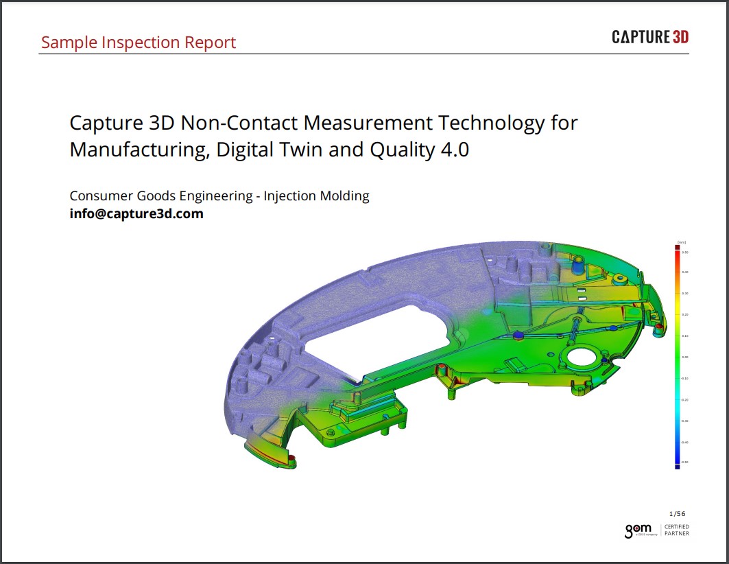
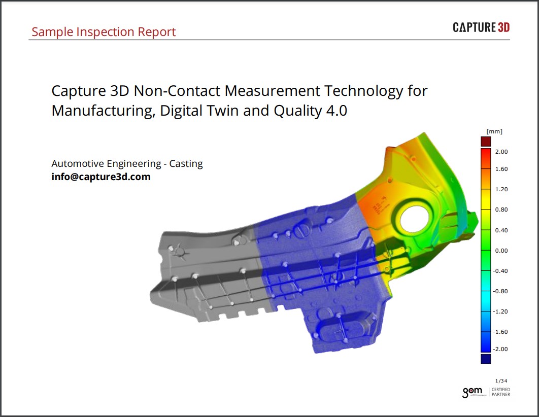
Learn how power generation companies are using accurate structured blue light 3D scanners, comprehensive inspection software, photogrammetry technology, and/or automation to improve manufacturing processes with rapid precision measurements
Doosan Heavy Industries & Construction is part of Doosan Group - the oldest and one of the most successful conglomerates in Korea. Doosan Group is active…
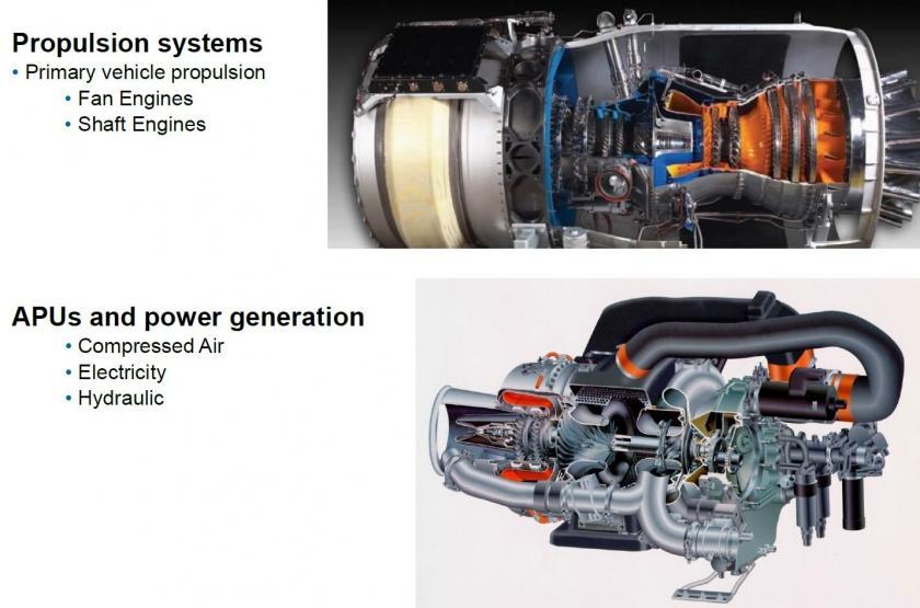
Honeywell is a leader in manufacturing aircraft turbine engine components and this presentation outlines their company background and a few case studies.
In this presentation by MTU Aero Engines describes how TRITOP photogrammetry and ATOS 3D scanner are utilized for measuring and the dimensional analysis of critical…
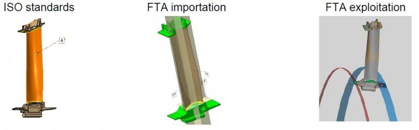
This presentation covers Snecma's importation and utilization of FTA, their encountered problems and solutions.
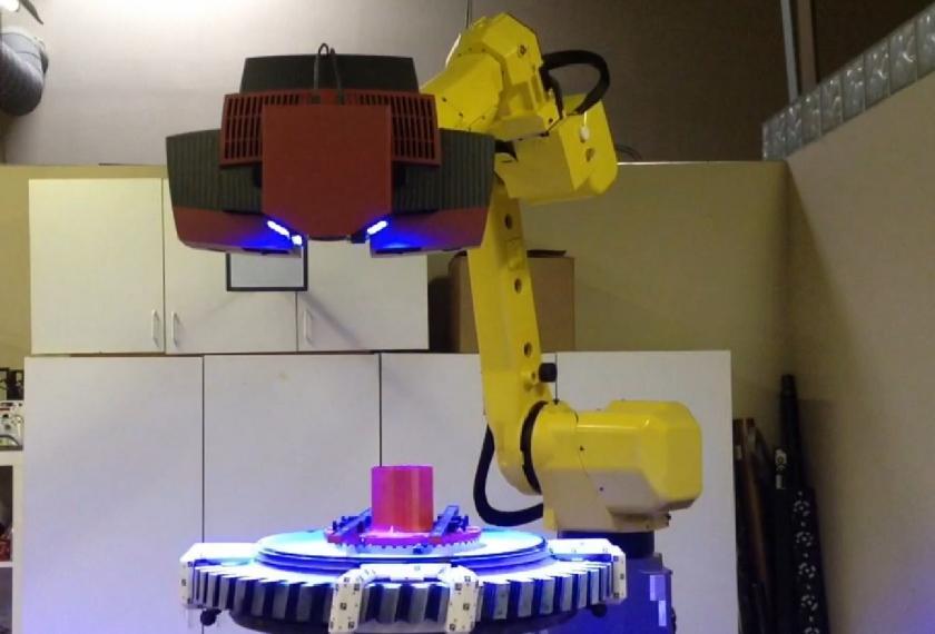
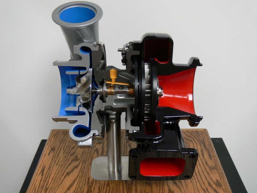
This presentation describes Solar Turbine's integration of ATOS from 2006 to 2014 incorporating automation for higher repeatability, throughput, and productivity for a variety of engineering…
This presentation describes Honeywell's implementation of ATOS for inspection of turbine engine components as well as a CMM comparison.