


ZEISS INSPECT
Effective tool for analysis
Operating with ZEISS INSPECT, the widely recognized standard in 3D metrology, our sensors seamlessly guide you through the complete workflow of scanning, inspection, and reporting.
Skip to main content

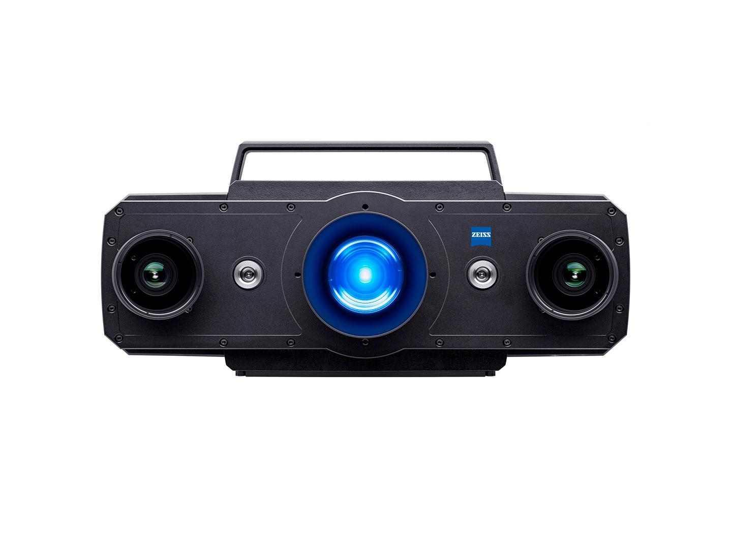
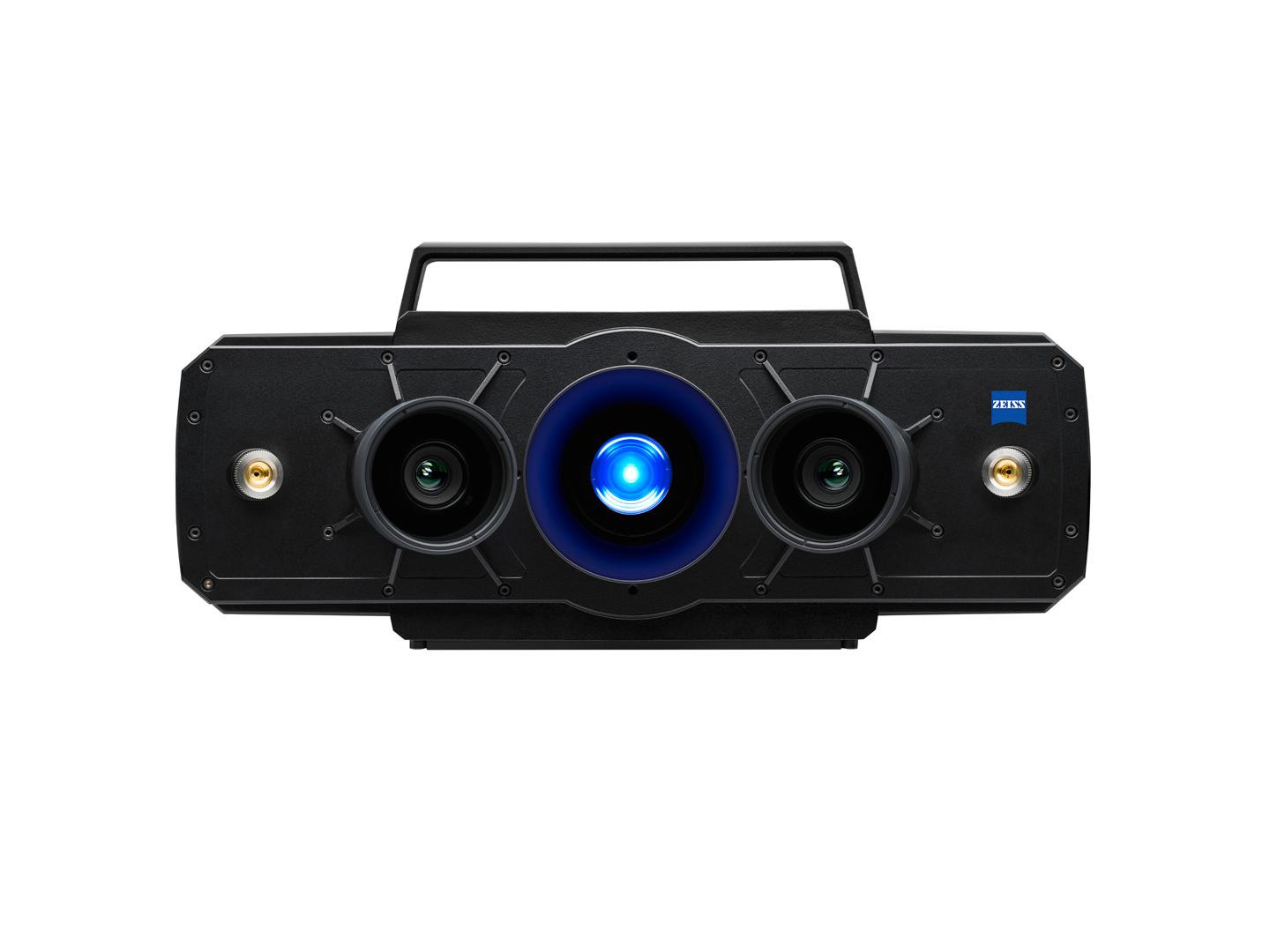
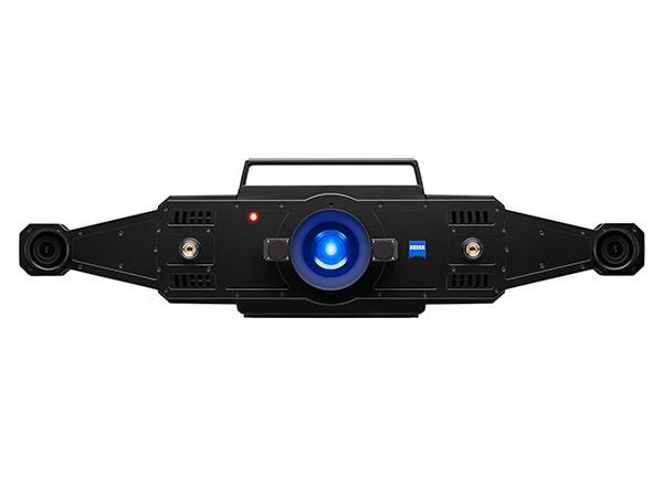
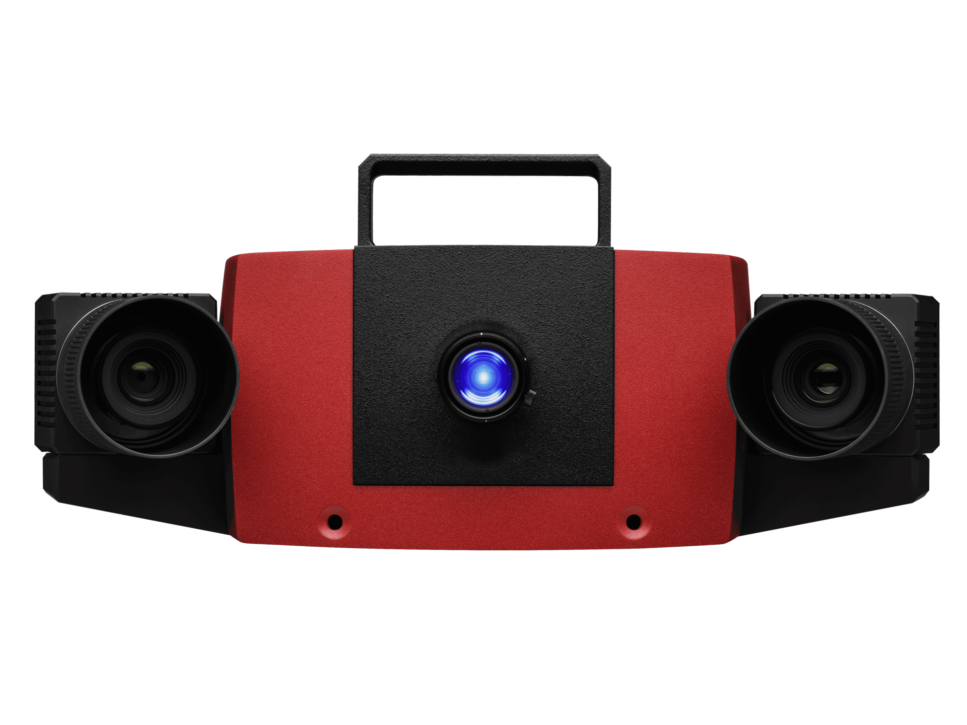
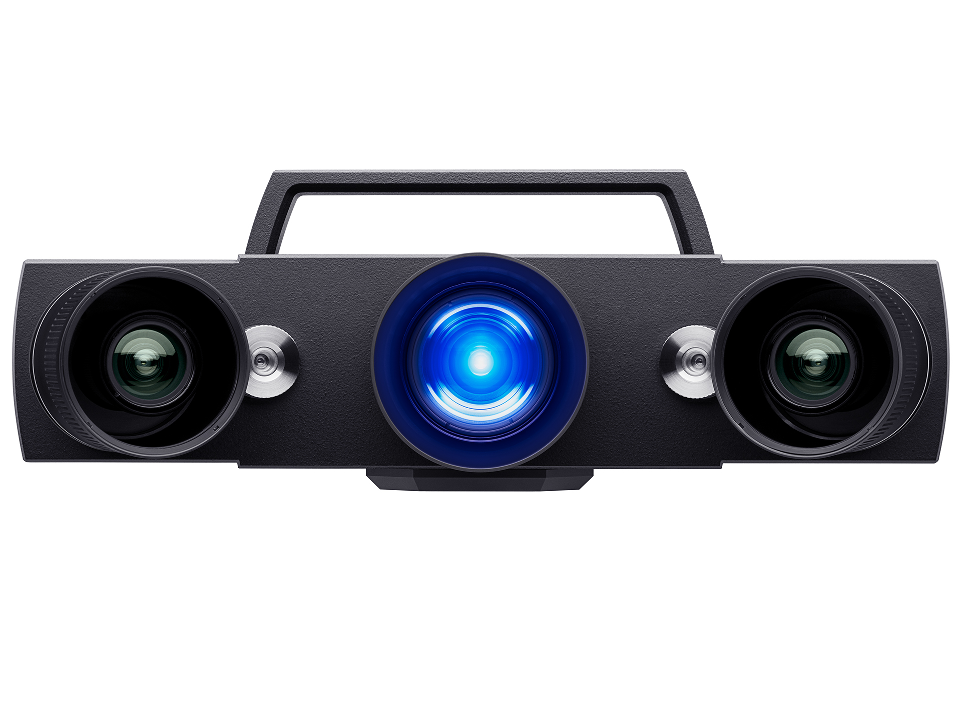
Get your hands on our versatile 3D scanning solutions at #HandsOnMetrology. Whether the hand-held 3D laser scanner ZEISS T-SCAN hawk 2, or compact and highly accurate 3D scanners, such as ATOS Q or GOM Scan 1 - at #HandsOnMetrology you will find the right solution for your 3D scanning task.