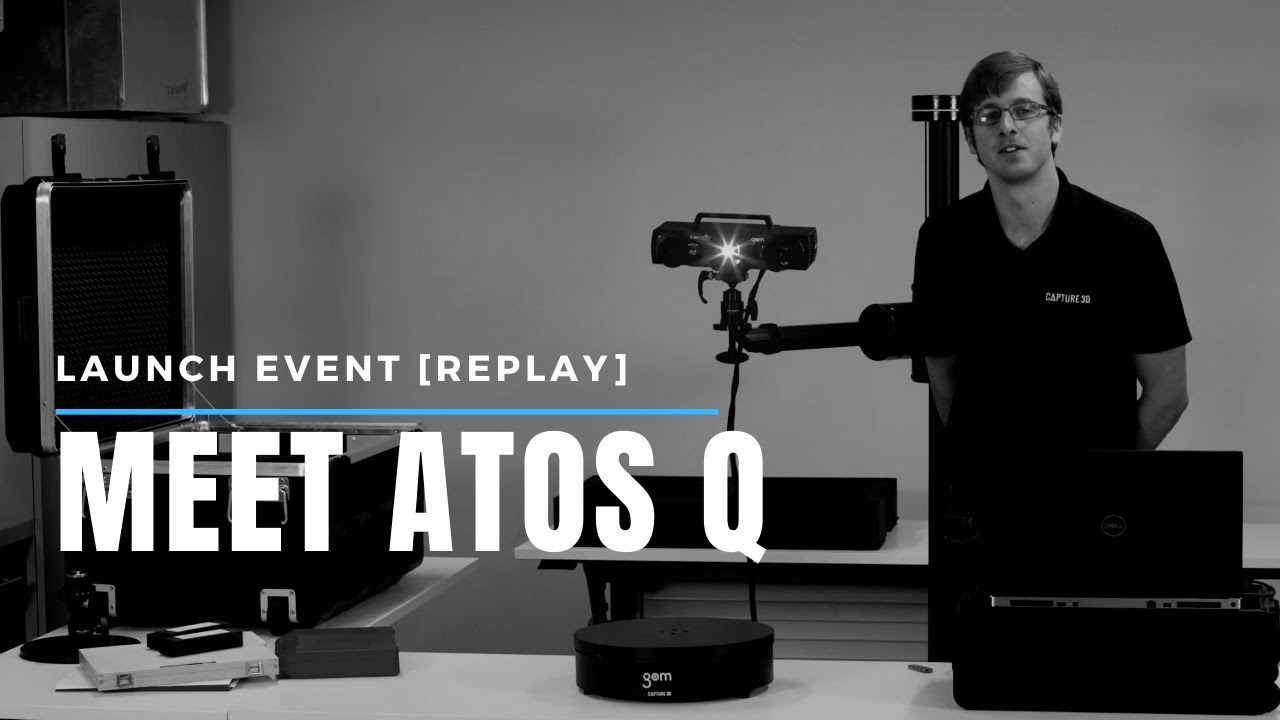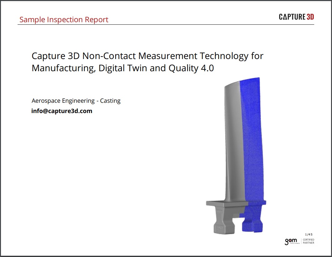
How to Project Actual vs. Nominal CAD onto Part (Back Projection) Using ATOS 3D Scanners
The GOM Software function known as back projection has many uses. For example, if you want to see the deviation of a surface comparison on a die, or have tooling that needs repair, or if you need to add a new feature to a prototype or an existing part that has an engineering change and an updated CAD model isn't available yet, you can accomplish this with an ATOS 3D scanner, GOM Software, and the back projection function. This combination provides the ability to project an element or features from the software onto the actual part, utilizing the projector from the sensor. For example, if you have one half of a die set or some tooling, and you want to determine if any repairs are needed, you can create a surface comparison and check this piece against the CAD model and then project those deviation zones back onto the actual part and visualize exactly where they are and where the repairs need to happen.
Step 1: Polygonize the Dataset
This tutorial uses a GOM training block. Begin by opening the software, pulling in the scan data, and polygonizing the dataset. After the polygonization is finished, the processed scans remain, which is now your mesh. Next, move into the inspection workspace, drag in the CAD, select Add to Part, and click OK. Then perform a prealignment to align the datasets. You can make the coordinate system invisible since you won't need it.
Step 2: Create a Surface Comparison on CAD
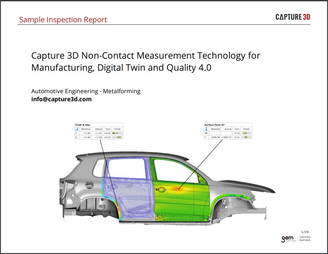
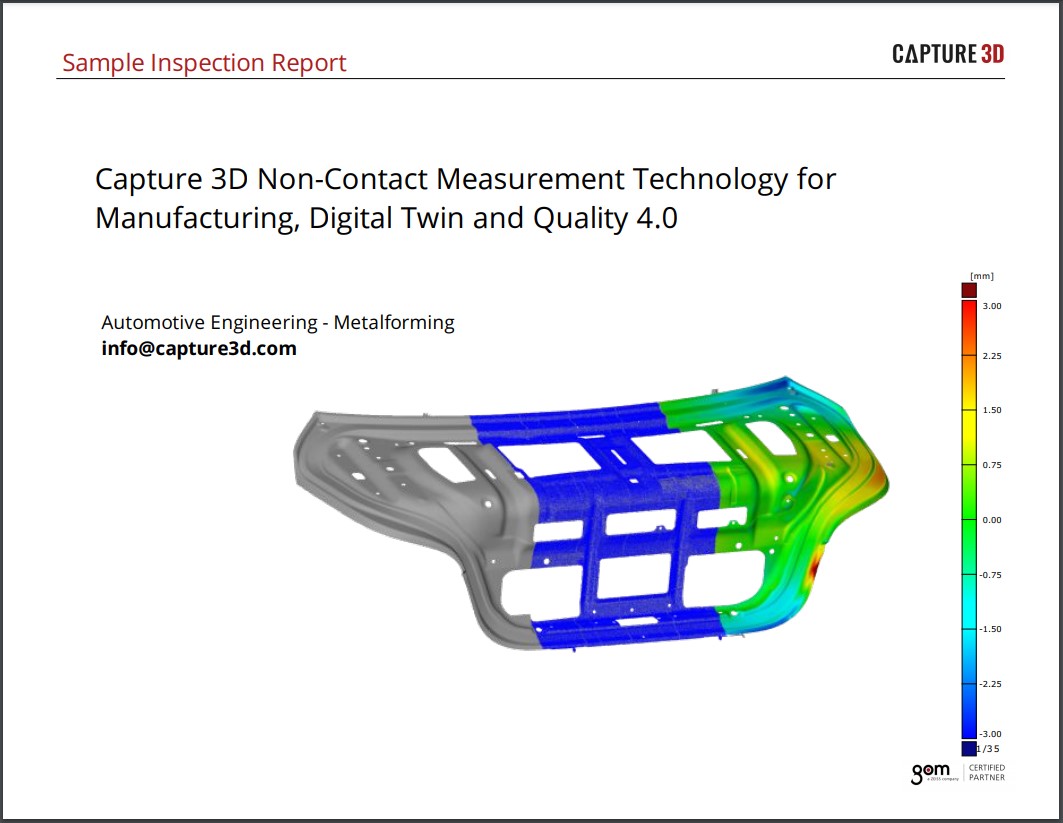
Next, navigate to Surface Comparison in the upper toolbar and create a surface comparison on CAD. Find that surface comparison and make it exclusive. Then right-click on the legend and go to legend templates and click on GOM 8 colors. Right-click on the legend again and go to Isolines and choose On Surface. Then click on the ledged to adjust the values to an acceptable deviation level, such as plus or minus .35. Now the deviation of the color map is divided into zones. Each color represents a zone of deviation, and now the Isolines can be projected onto the part.
Step 3: Project Isolines onto the Part
Next, move into the Live workspace on the left side of the screen. Many things can be done in this area, such as defining a component, which you would use when a piece gets assembled into another piece. Then, you would put reference points on it to help you position it correctly to the mating piece. There is also a function for Touch Probe Measurements, which allows for the measurement of features such as circles, slats, cylinders, and planes. For this example, use the Project Elements on Measuring Object function to project the surface comparison onto the measuring object. All these functions require using previously collected reference points. For the projection mode specifically used in this example, the reference points allow the Isolines to be projected into the correct position.
Next, click on Surface Comparison in Explorer to highlight the surface comparison, and go to Project Elements on Measuring Object. The function provides an option to pick the thickness of the Isolines lines that will be projected. For this example, choose medium. Notice that the boundary lines for the deviation zones are defined by the legend with color and notice the projection through the live view. As you move the part, the projection moves as well because the software uses and remembers the reference points you collected. Notice that you can rotate the part, and the lines will be placed in the correct location and orientation.
Step 4: Mark Areas of Interest Directly on the Part
Now you can mark any areas of interest directly on the part. For this example, mark the area at the top of the part and the bottom. These zones are both in the red, and you could make a note to remove .35 millimeters of material because the area is above the CAD. Alternatively, the blue zone in the middle of the part needs .25 millimeters of material added because it's below the CAD model.
How to Use Back Projection if You Need to Add a Feature to a Part
Another situation that you may use back-projection for is if you need to add a feature to a part, such as a prototype or an engineering change requiring initial analysis. Begin by projecting the nominal elements onto the actual part. In this instance, you don't need process scan data because you only need one or two scans. Take a scan and identify the reference points for use later in the process. Next, drag in the CAD and click Add to Part. Then create a prealignment to align the scan data with the CAD. Next, make the CAD exclusive and drag it into the 3D view. Go to Construct Surface Point and click the CAD in some arbitrary place. In the dialog box, click the dropdown where the coordinates are, edit the values to a known value, and consider rounding the numbers, so it's easier to understand. Then select OK. In the dropdown menu labeled Normal, select Z+ for the direction and hit Create And Close to complete the surface point on CAD. Give it a measuring principle of No Measuring Principle because it's just a nominal feature.
Then go to Construct, then Circle, then Point-Normal Circle, and select the label for the point and the normal direction, both being the surface point you created. Then give it a known diameter. Next, open the Explorer, go to the nominal elements and find and select the circle and surface point by holding down the CTRL key and clicking on each label. Give the circle No Measuring Principle as well. Go to Project Elements onto Measuring Object and select medium. In the live image view, you'll see where the circle with a crosshair is projected onto the part. The crosshair is there because you selected the surface point as well. You could also mark it on the part to take it directly to a drill press or a punch to create the hole in the part.
How to Take Your Digital Engineering Skills Further with GOM Software
Following this process, it only takes a few minutes to create either an inspection or a new feature that can be projected directly onto a part for use in steps further in your process. This function is just one of the many ways that GOM Software rapidly increases inspection efficiency and digital engineering capabilities. ATOS and GOM Software technology enables you to take full advantage of digital twins. To learn more about GOM Software or see a demo of the latest ATOS 3D scanning technology, contact a Capture 3D team member today!