Automotive
Case Studies
Learn how automotive companies are using accurate structured blue light 3D scanners, comprehensive inspection software, photogrammetry technology, and/or automation to improve manufacturing processes with rapid precision measurements
ADAC Automotive first opened its doors in Grand Rapids, Michigan in 1975. Back then, the small company was known as ADAC Plastics. Today, ADAC Automotive…
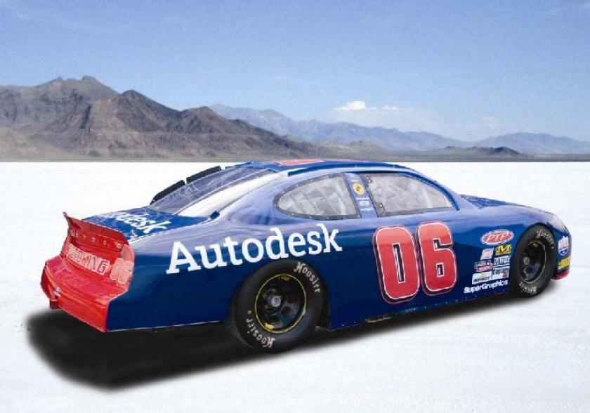
This presentation explains how TRITOP photogrammetry and ATOS were used for CFD analysis to help reach world record speeds of 200+ mph.
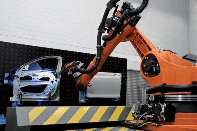
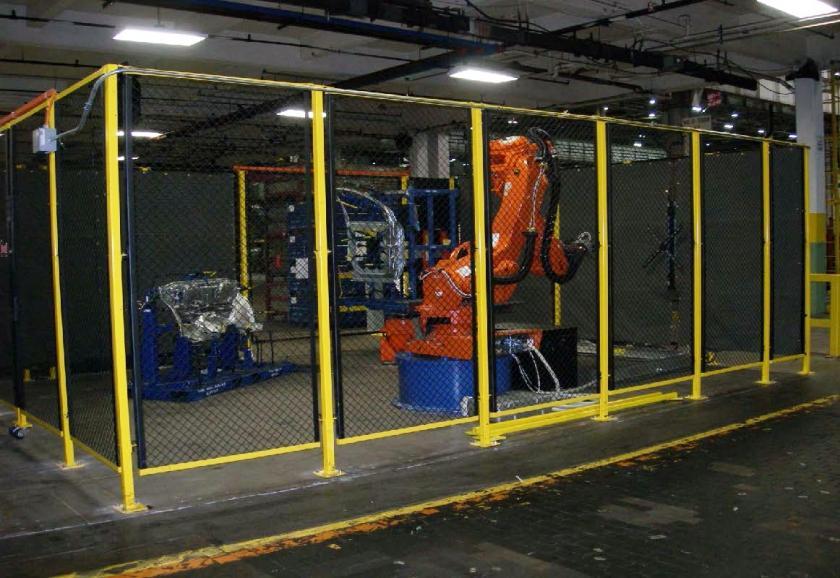
In 2006, BMW delivered a presentation at the GOM International Users Conference enlightening the audience on their vision into automated robotic metrology for inspection of…
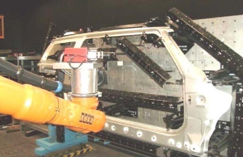
The press shop at BMW‘s Dingolfing plant relies on optical metrology systems including automation and standardization for inspection of shee t metal components. Here, 3D…
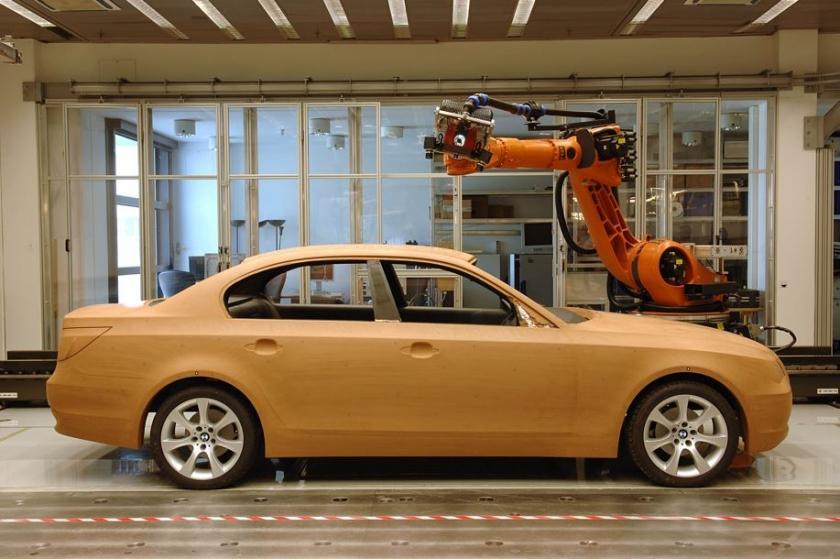
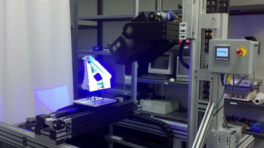
In 2007, BMW presented on their automated ATOS scanning robotic solution for the automotive design application.
This presentation by BMW describes their die panel inspection process as well as a comparison to CMM versus ATOS structured light 3D scanning. Every panel…
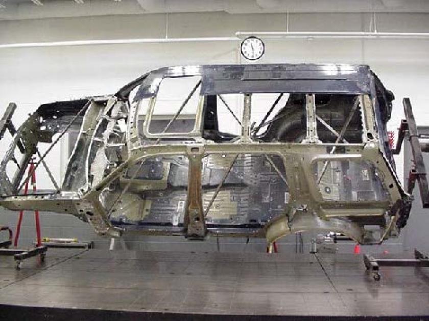
Mobile optical 3D coordinate measuring technology is used for quality assurance on the production line in the BMW Regensburg plant. For the assembly of roof…
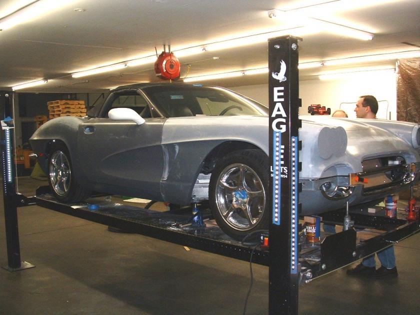
Boeing REsolutions presentation discussing process for reverse engineering and designing a classic Corvette body onto a newer model using ATOS for 3D scanning to create…
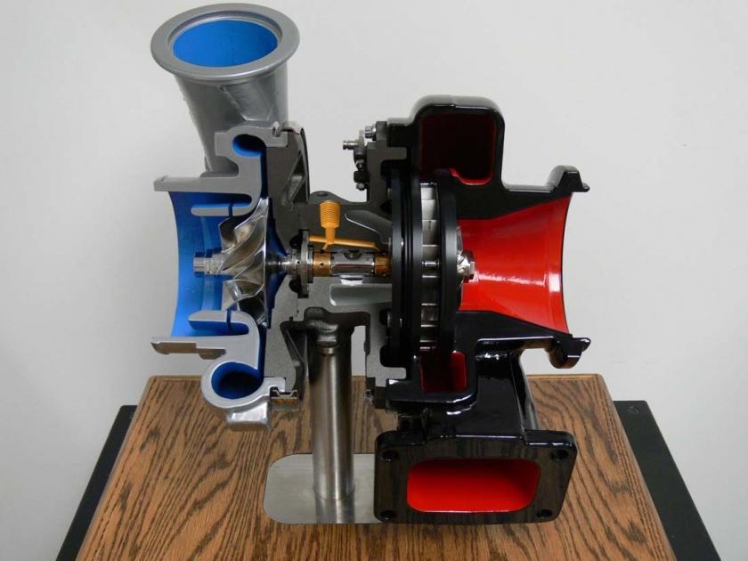
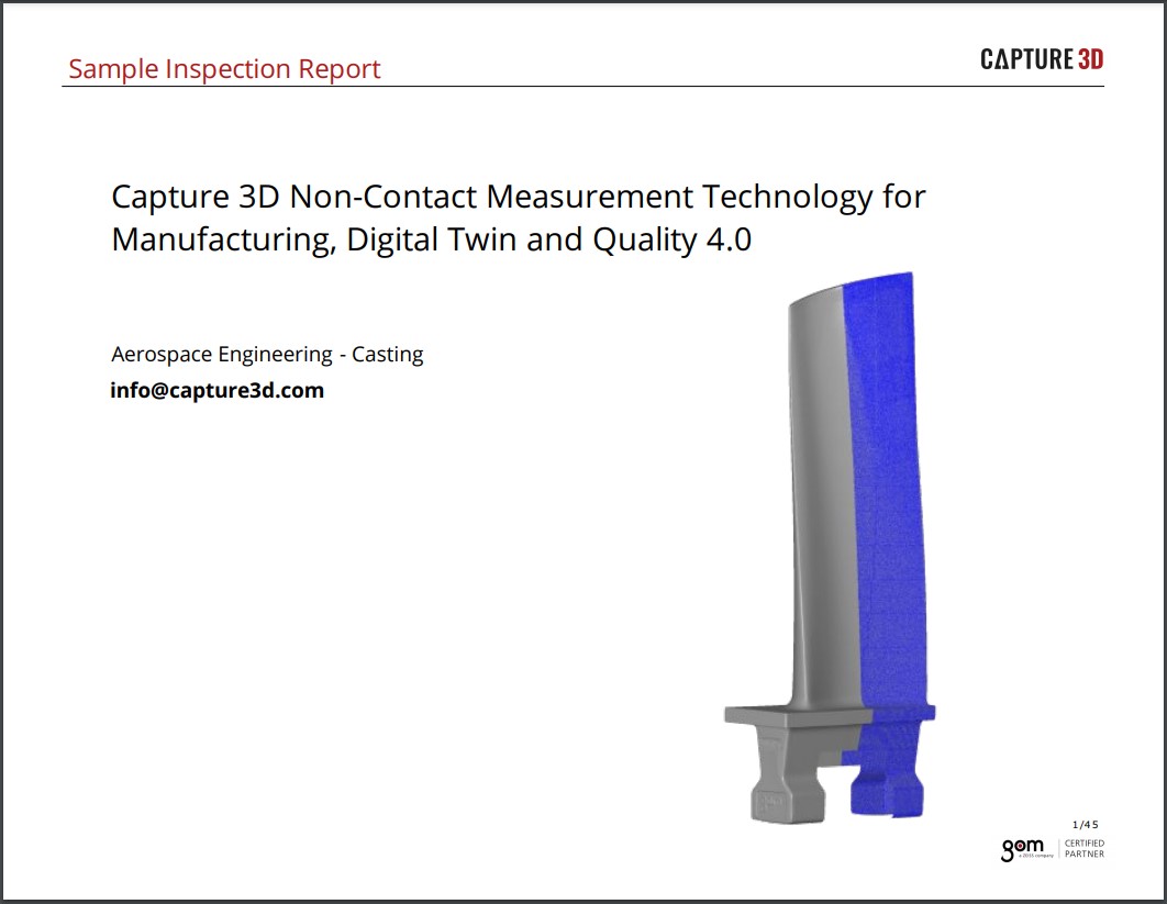
This presentation describes Honeywell's implementation of ATOS for inspection of turbine engine components as well as a CMM comparison.
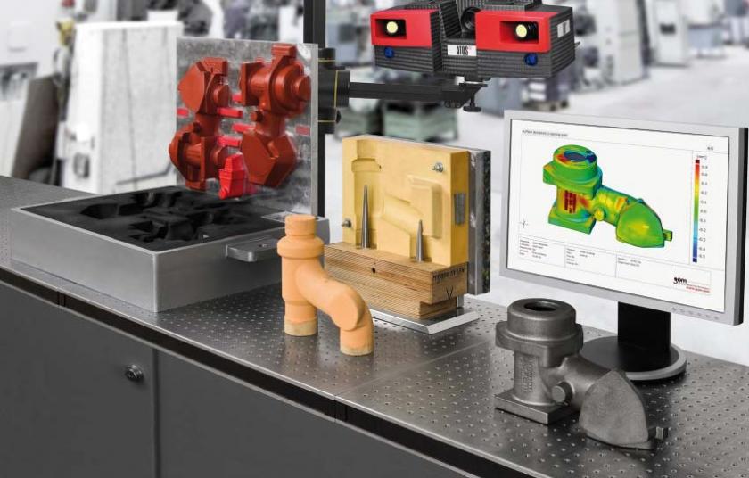
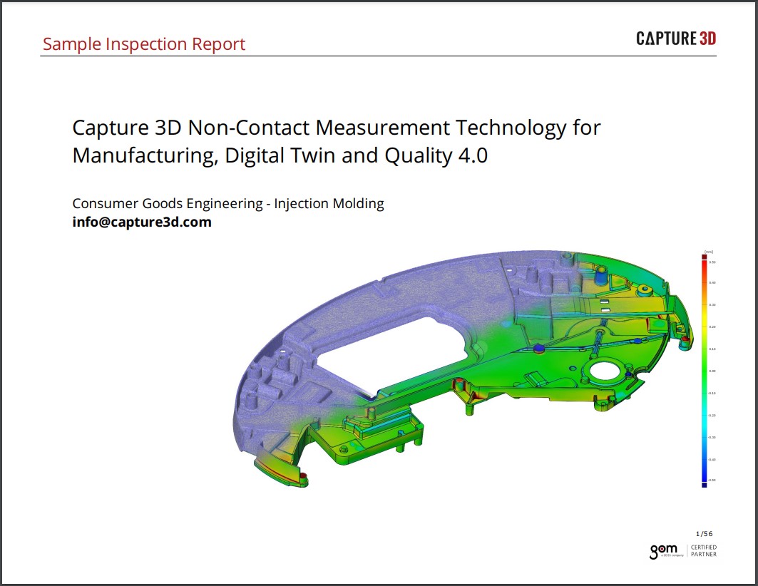
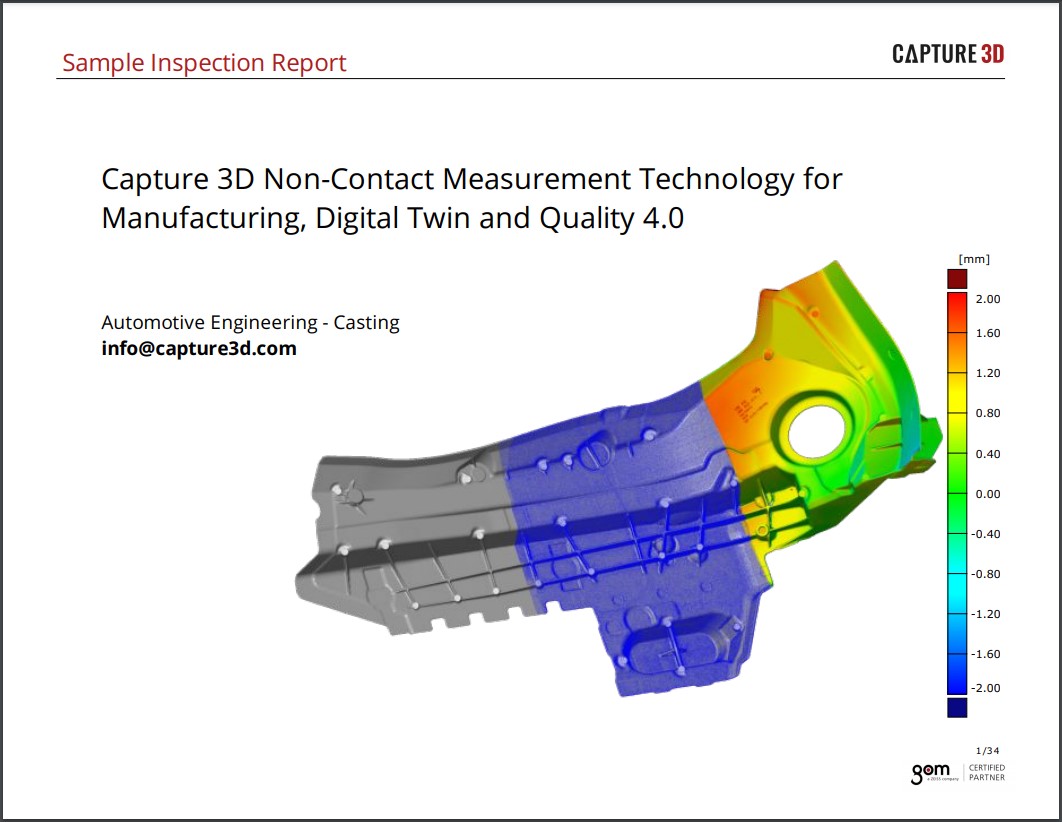
Already before the first article inspection (FAI) of the casting, 3-D shape and dimensional analyses provide reliable information for quality control and targeted process optimization.…
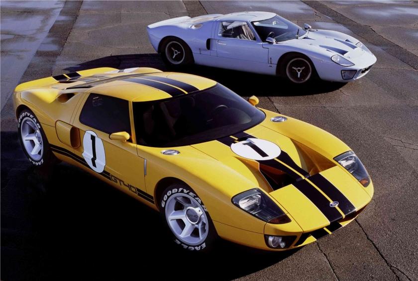
It was in France in the mid-1960s that the great American supercar came to life. A low-slung, muscular racing car built to win on the…
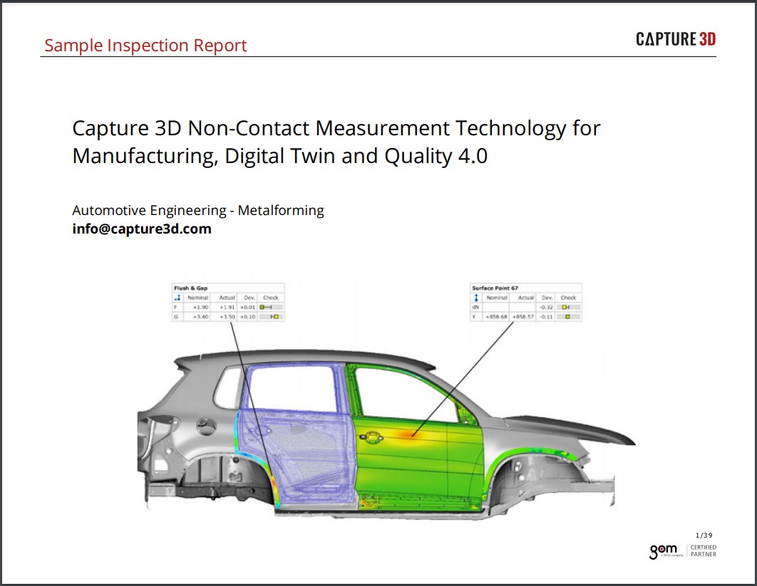
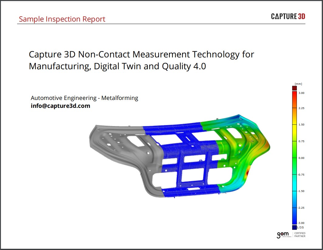
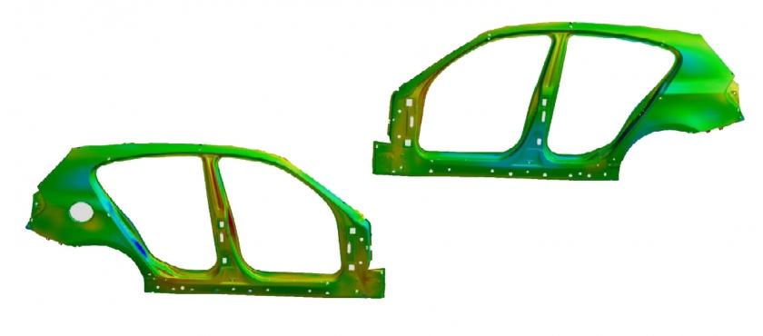
Ford Stamping engineering has identified 14 key areas where white light scanning is an enabler to improve timing and quality –process improvements. Systematically going through…
The automotive supplier GEDIA is taking a new approach to quality control. The company is replacing measuring technology based on tactile systems and gauges with…
Dimensional analysis of the prototype molds was conducted with the aid of an ATOS Triple Scan optical 3-D digitizing scanner equipped for blue light scanning…
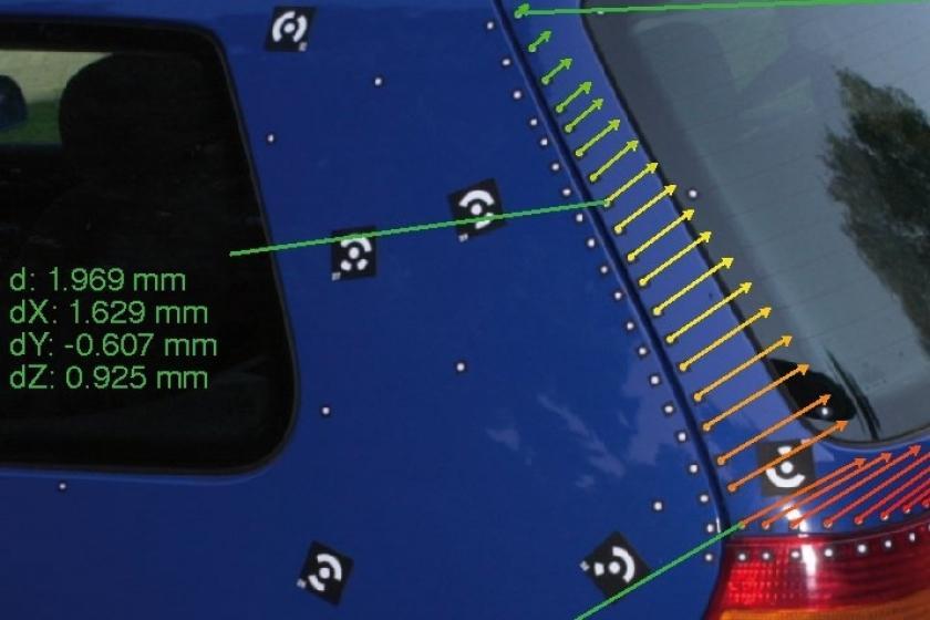
This example shows how the photogrammetric system TRITOP is used for local as well as global deformation analysis by the automotive industry.
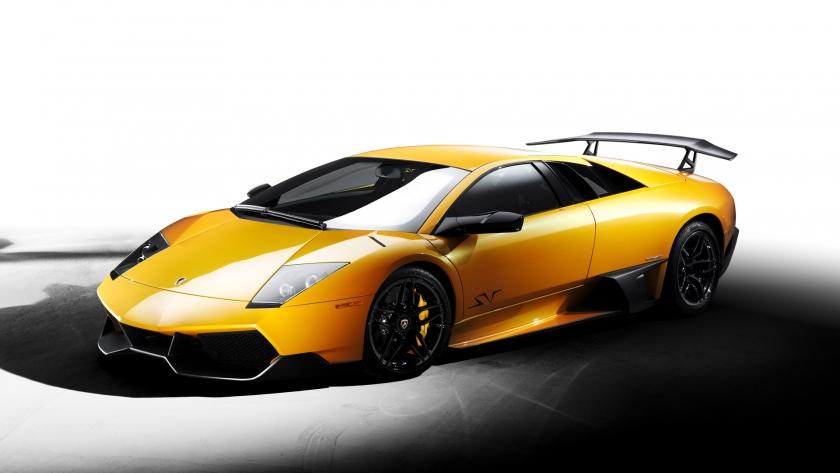
Lamborghini explains why they chose ATOS for 3D scanning applications such as reverse engineering and inspection of their luxury super sports car, and gives a…
This presentation given in 2012 continues from their last presentation in 2010 to cover the further enhancements and improvements Mann+Hummel have achieved by purchasing an…
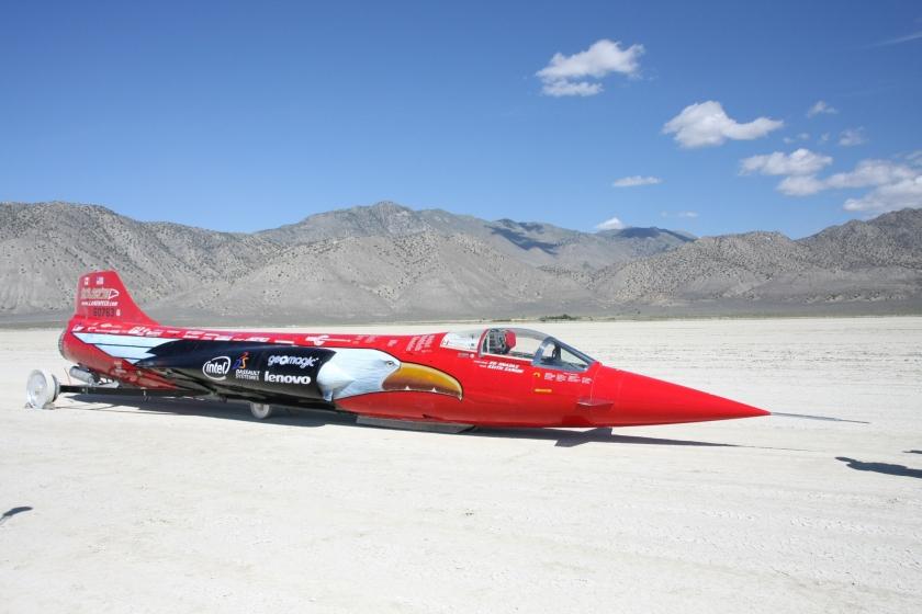
North American Eagle asked Capture 3D to help create a digital model of their vehicle for CFD analysis to help in their attempt to break…
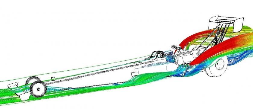
Penske Technology Group's presentation regarding utilizing ATOS for reverse engineering and CFD analysis for improving top speed.
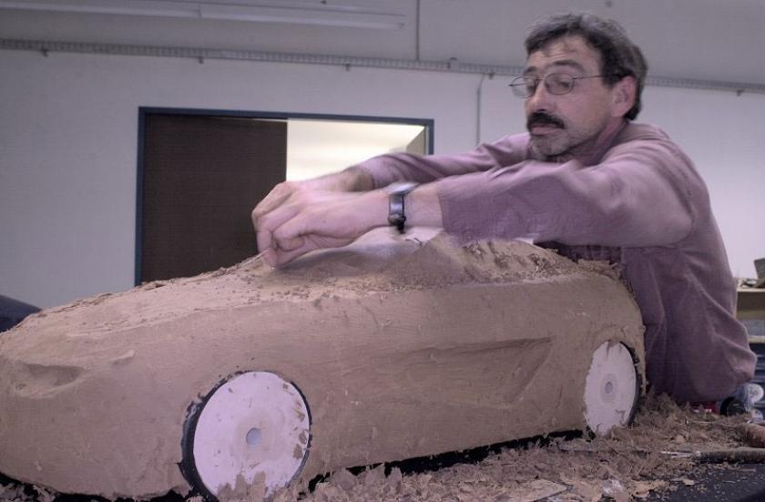
A typical application for 3D digitization is the recording of the actual shape of a physically existing model during the design and product development phase.…
This presentation discusses the competitive vehicle digital benchmarking process of vehicle disassembly, 3D scanning, post processing, data compilation, and deliverables.
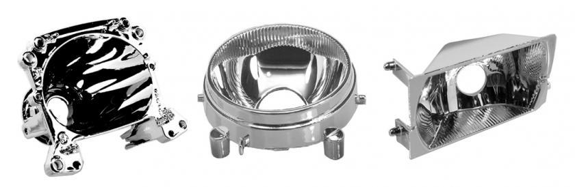
A travel into the die-casting and metallization technologies of aluminium die-cast reflectors for the automotive lighting industry- fog lamps, head lamps, heat dissipators, containers for…
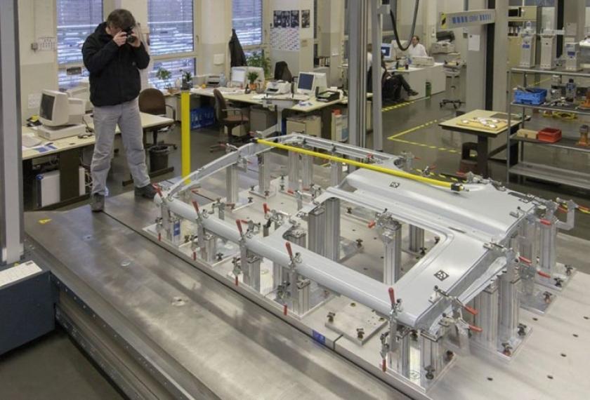
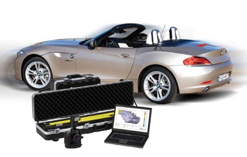
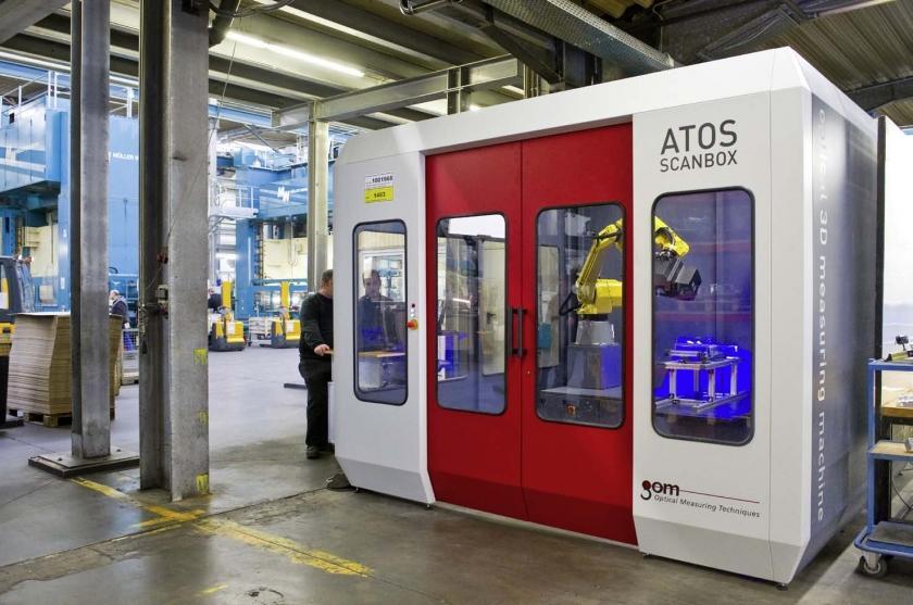
Measuring tasks that so far could only be performed using tactile 3D coordinate measuring machines, measuring arms or measuring aids, can now be carried out…
The focus of the presentation was the mutual project from Volkswagen and GOM in the area of optical in-line measuring technology, with which the production…

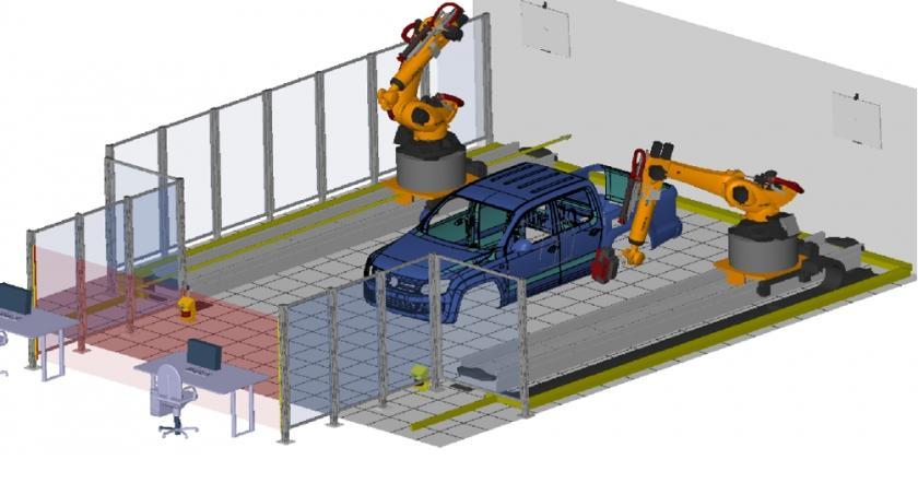
Volkswagen | Robot-supported Measurement of Suspension Parts - Automated Operation of an ATOS Sensor
In 2007, Volkswagen presented on their automated ATOS scanning robotic solution for the inspection of their suspension parts.