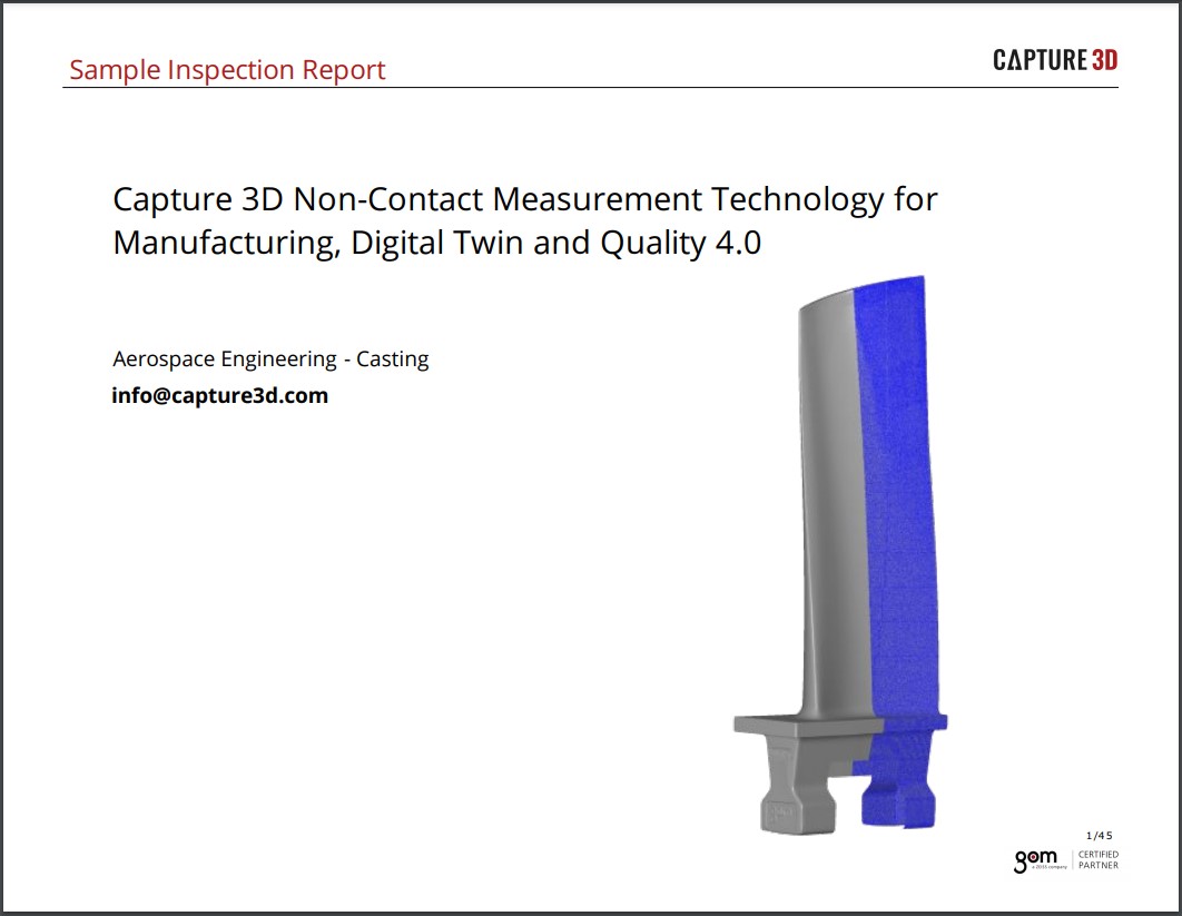
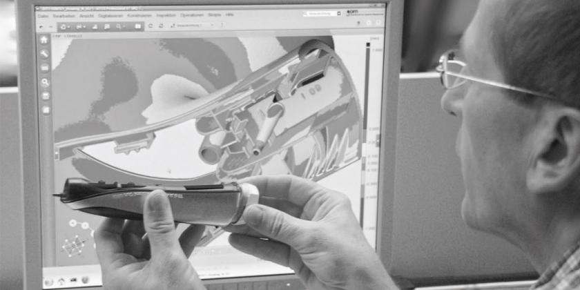
 Fig. 1: The ATOS 3D scanner captures the entire surface of the part instead of just a few individual points. For a complete evaluation Braun uses the GOM inspection software. With its parametric kernel, the software executes inspection processes automatically for components of identical design.
Braun
Images Replace Numbers - Quality Assurance of Plastic Parts with 3D Measurement
![]()
![]()
The product portfolio of the Procter & Gamble subsidiary includes electric razors, epilators, and hair and dental care appliances under well-known brands such as Gillette and Oral-B. Braun has already taken numerous prizes for the design of its high-quality products, and gives priority to precision and dimensional accuracy during manufacturing. In the past, contours of parts were based on geometric primitives but have gradually been replaced by free-form surfaces. The relevant inspection plans, however, still consisted of figures from a 2D technical drawing.
Inspecting the individual elements from drawings during quality control was highly work-intensive and full-field part inspection was not yet possible. The company therefore opted to migrate to optical metrology. Today, Braun uses the ATOS 3D scanner in conjunction with the GOM inspection software. The software has a parametric kernel which stores links and creation paths of individual elements, for example as a complete evaluation. This means that a second part can be assigned the same evaluation without the need for further programming, thereby simplifying above all recurring measurement tasks. Operators simply load the measurement data (STL triangular mesh) and press the update button. Inspection then runs automatically on the second part and includes creation of the evaluation report. When changes are required in the measurement program, they are automatically transferred by the parametric system to all the elements involved. Hundreds of parts are measured and evaluated in this way at Braun today – during the standardized first article inspection and pre-production inspection processes. (Fig. 1)
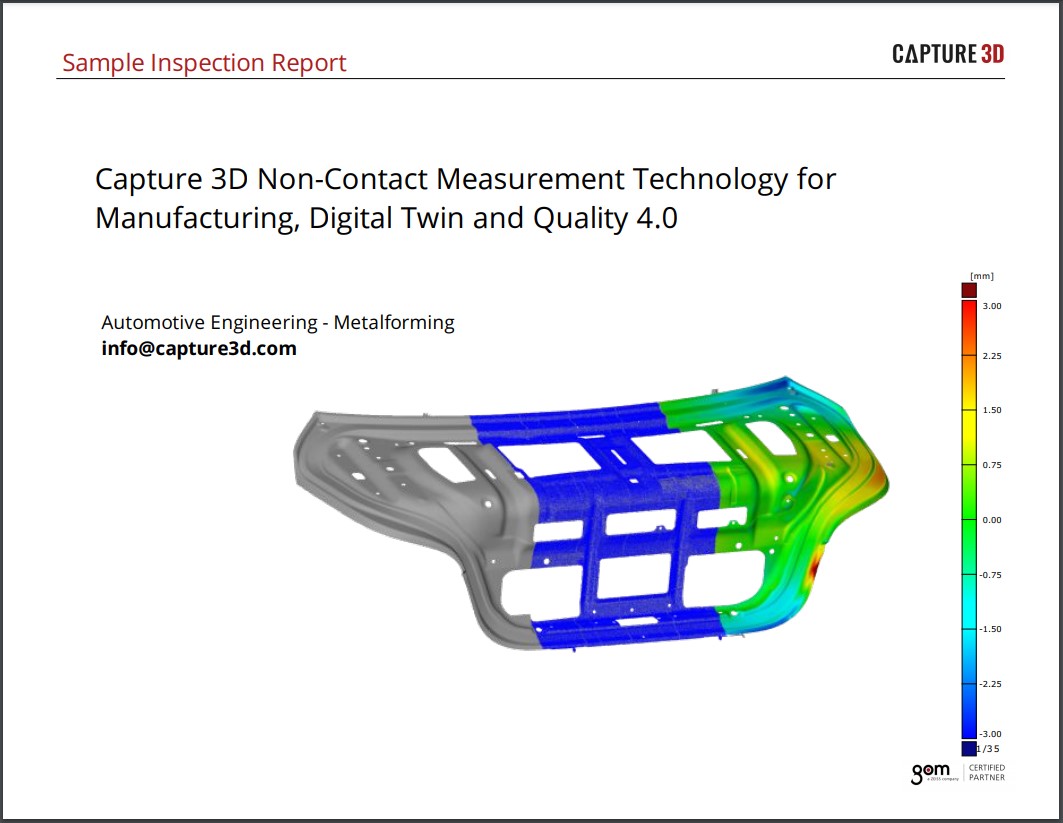
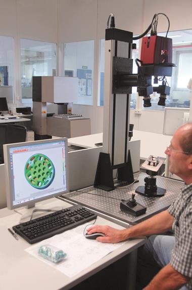
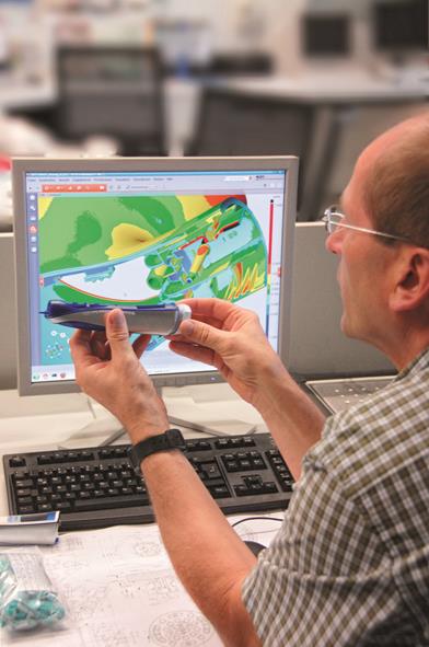 Fig. 2: During evaluation, deviations from CAD data are highlighted in color, producing self-explanatory corrective measures in easy-to-understand measurement reports.
Full-field part digitizing
The ATOS 3D scanner captures the entire surface of the part instead of just a few individual points. During evaluation, deviations from CAD data are highlighted in color, producing self-explanatory corrective measures in easy-to-understand measurement reports. With optical measuring technology, Braun also gains far more information than before, no longer just point-to-point distances expressed in figures, since each part is now digitized and displayed completely. This has made it possible for Braun to cut first article inspection for a disc brush for electric toothbrushes from a 32-cavity tool by half compared with the previous process. Tactile measurements of these parts would take far longer and only supply point data. Another advantage is that Braun can exchange all its measurement results inside the company with the free GOM Inspect software and also evaluate it together with other production facilities, all of which accelerates the decision-making process. (Fig. 2)
Specific tool corrections
Optical metrology is used not only for first article inspection but also for tool correction. To fulfill the high optical and haptic requirements for its products, Braun uses metallic coatings in addition to various materials during manufacture. As a result, the plastic parts have different geometric properties after coating. They may also warp as a result of mechanical tensioning. Such parts are now measured before and after coating in order to reveal shrinkage and warpage compared with the CAD model, and therefore to reveal any corrections which the tool requires.
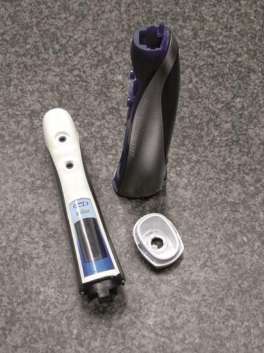 Fig. 3: Especially these housings change their geometric properties after mechanical tensioning and galvanizing. Since tactile methods only sample individual points, these parts used to be very difficult to measure and evaluate. Furthermore, it was almost impossible to measure the 3D seals that Braun integrates in these parts using tactile measurements.
The full-field measurement data also offers advantages for partially coated or insert molded parts. Since tactile methods only sample individual points, these parts used to be very difficult to measure and evaluate. It was almost impossible to measure the 3D seals that Braun integrates in some of the parts using tactile measurements. (Fig. 3) This made tool corrections a time-consuming process for design engineers as well as tool makers. It is vital for the design engineer to be able to make changes to the CAD model to ensure that the end product can be produced with the correct dimensions.
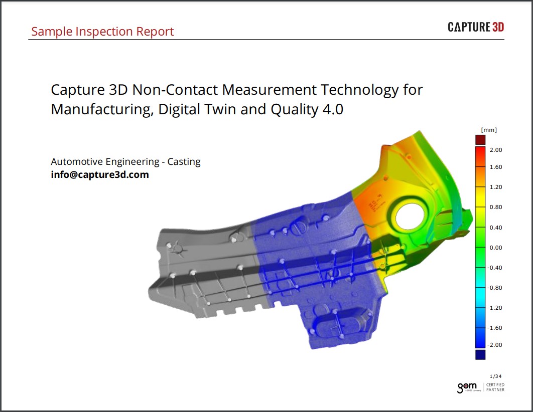
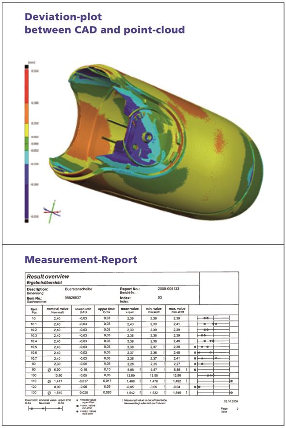 Fig. 4: One image says more than a thousand numbers. With optical metrology, sink marks, misaligned ejectors, protruding gates or even component warp can be identified, localized and supported with data.
Simplifying technical drawings
Another use for optical metrology at Braun is to identify potential problems that commonly occur on injection molded parts, such as sink marks, misaligned ejectors, protruding gates or even component warp. The results of full-field measurement make it possible to identify these promptly, to pinpoint their location and support them with data. This is a great advantage for mold makers since they quickly see whether and how they need to intervene in the tool geometry, or whether parameters on the injection molding machine need changing. With the full-field surface comparison against CAD data, the experts at Braun can now even detect whether a specific problem lies in the tool or in the injection molding process.
Since Braun rolled out optical measurements, it has been able to simplify its technical drawings and inspection reports. Whereas previous inspection plans consisted of columns of figures, the full-field data base and transparent evaluation showing deviations from CAD in color now make for far simpler visualization of the evaluation results. Several hundred pages of conventional tables from test reports can be reduced to a handful of images and functional dimensions. As a result, technical drawings can be simplified in advance. To provide a fast overview, the full-field measurement data of a component is compared with CAD data. The inspection elements are reduced to functionally relevant functional dimensions and GD&T elements and then inspected. (Fig. 4).
3D measuring technology enables Braun to guarantee the dimensional precision of the design for all free-form surfaces, specific dimension adjustments during the galvanizing process and the dimensional inspection of all its parts. Another advantage is that it can simplify its technical drawings and inspection reports.