GOM
Optical 3D Measuring Techniques and Inspection Software for Quality Control of Sheet Metal Components
White Paper

Quality assurance and management are growing in importance in industrial development and production. The decentralized production of components by suppliers mean that tight specifications have to be meet to ensure problem-free assembly in final production, resulting in a high-quality final product. As such, optical digitizing systems have become firmly established for inspection of indi- vidual sheets, in assembly analysis, and during forming tool try out.
Industrial optical 3D measuring technques
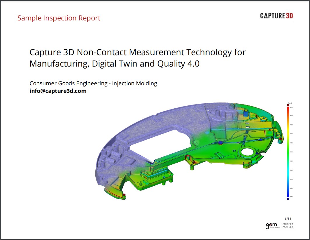
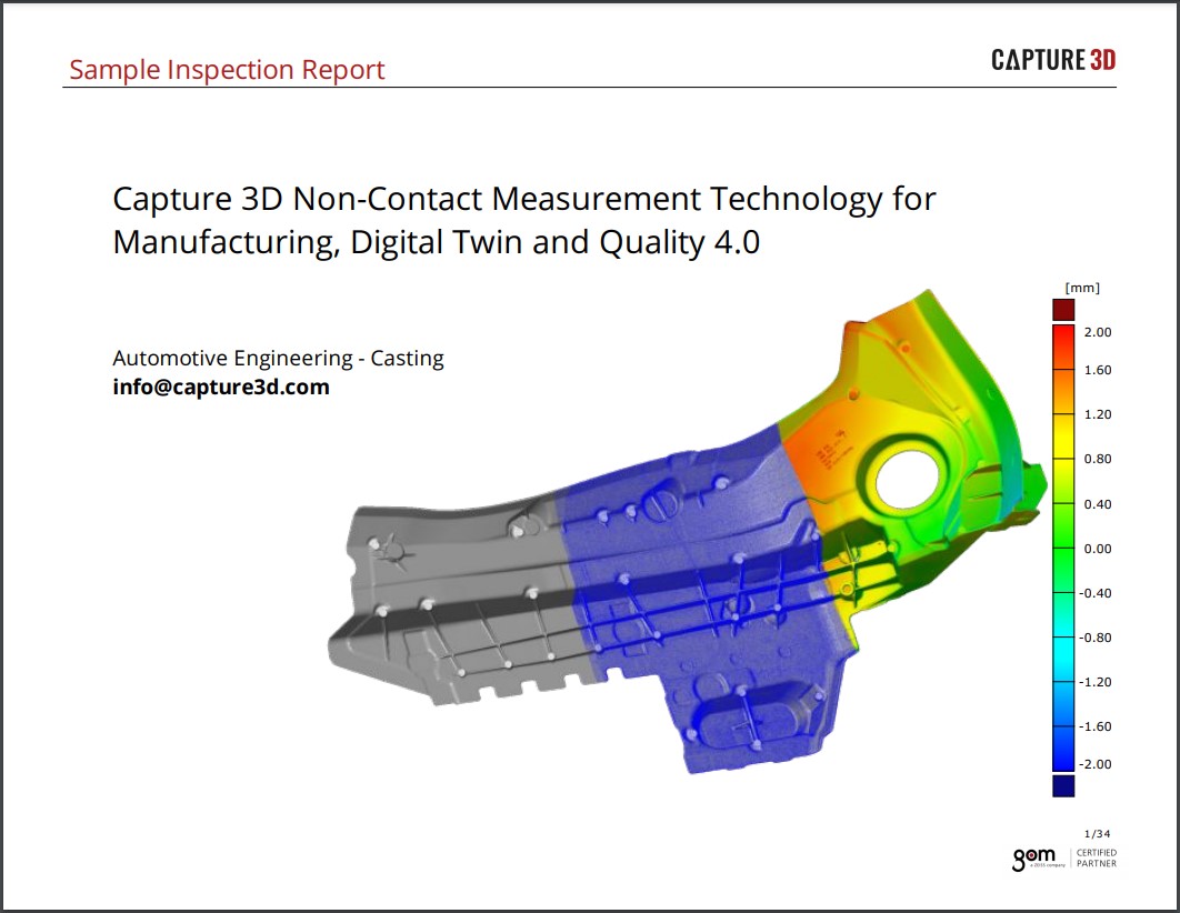
Previously, sheet metal parts could be inspected by tactile measuring machines in only a few locations due to time limitations. In contrast, optical 3D measuring techniques acquire the entire component surface geometry using a high-resolution point cloud.
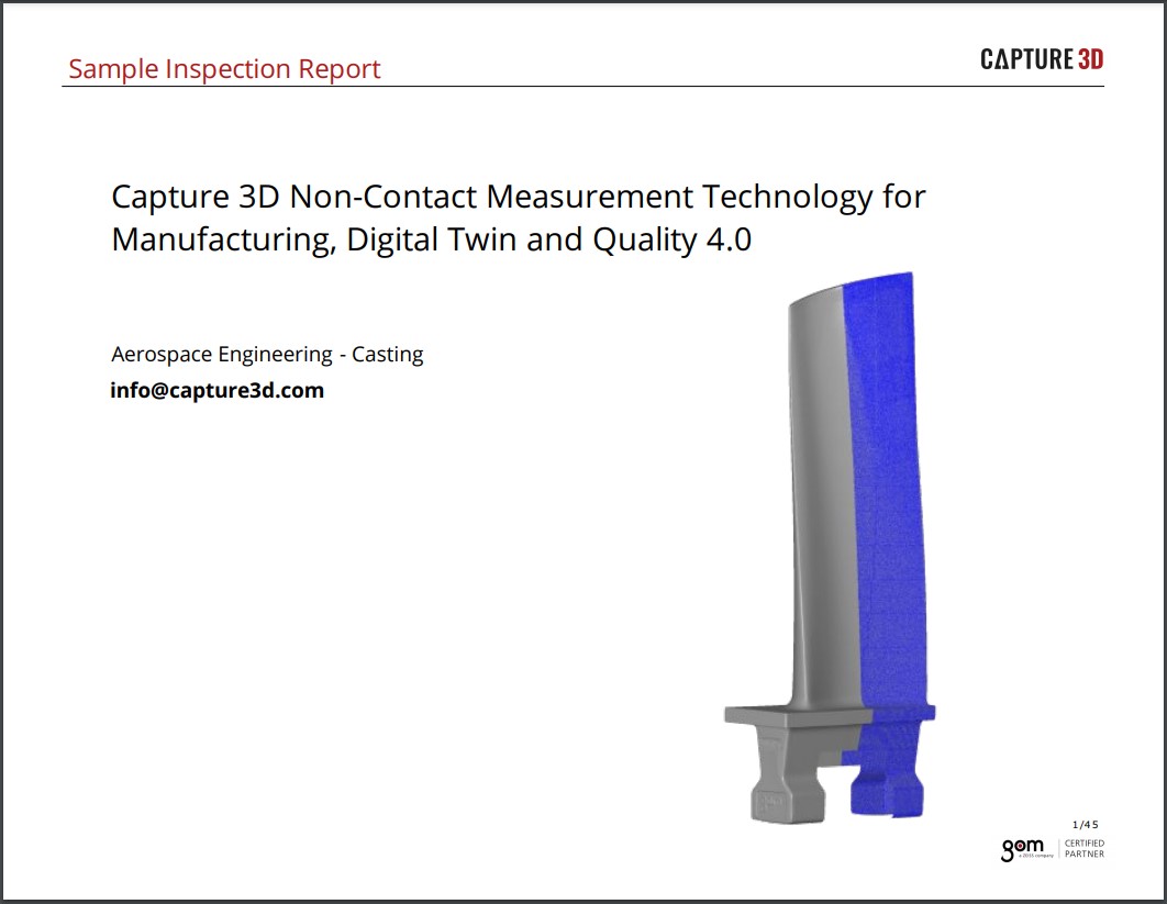
The ATOS 3D Digitizer is used as a precise, fast, and robust measuring solution by companies from the consumer product area, aerospace and automobile industry, including BMW, Audi, and Volkswagen. ATOS combines high-quality measured data with flexibility, and can be used not only in the measuring rooms but also in the pressing plant and raw production environments. Regardless of object size, precise 3D coordinates are created and complete measuring and inspection reports delivered.
 With guided feature recognition, measure all features with certainty
Until recently, the measurement of sharp edges required the use of coordinate measuring machines because optical digitizing systems provided unsatisfactory results. But thanks to complete, in-house development of sensor, measuring, and inspection software, a comprehensive concept and secure workflow, specifically for the entire sheet metal inspection process, could be developed.
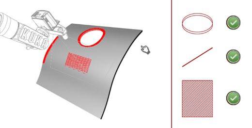
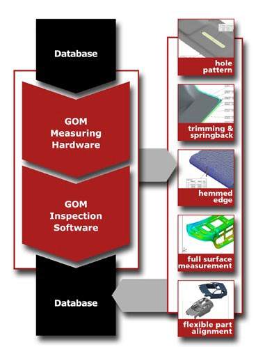
Typical features such as hole patterns as well as trim and springback at borders can be measured with ATOS using the "Guided Feature Measurement Strategy." Using the inspection features previously extracted from the CAD, the software shows the user the best sensor positions, for example, in which an elongated hole can be measured optimally. Even sharp-edged features can be measured reliably with subpixel precision, using specially developed algorithms.
|
|
Jigs and fixtures
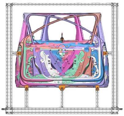
Stable parts can be measured without jigs or fixtures using the contact-free ATOS Digitizer, because the alignment of measured data to CAD data is controlled using RPS points in the ATOS inspection software. If a sheet metal component is digitized when free standing and once installed, deformations can be measured and visualized. Variable alignment is possible due to the dense data volume, and contributes to fast problem resolution during assembly analysis.
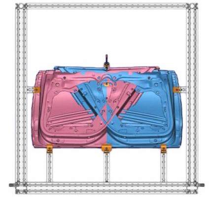
For the measurement of clamped sheet metal components, the contact-free measuring techniques enable an adaptive fixture concept, thus saving costly gauges. For example, a simple holding jig can replace six measuring gauges. Since it can be used in parallel for various parts, storage space and production time are saved.
|
|
GOM ATOS inspection software: a comprehensive concept from measuring plan to measurement and evaluation
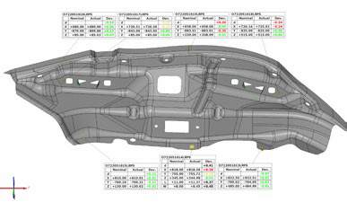
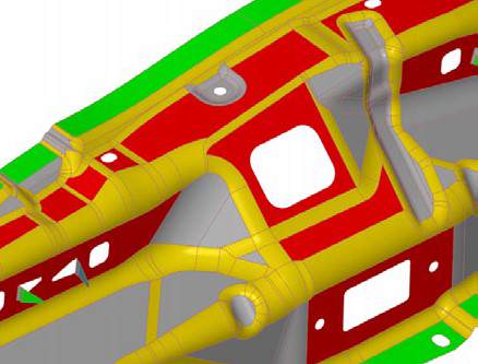
ATOS inspection software enables CAD formats to be imported, in addition to classic measuring plans such as Catia-List, DMIS, etc. In addition, inspection features that have already been implemented in the CAD data can also be entered, for example surface tolerances, profile, shape, and position tolerances.
|
|

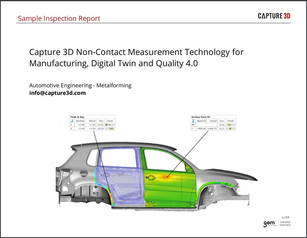
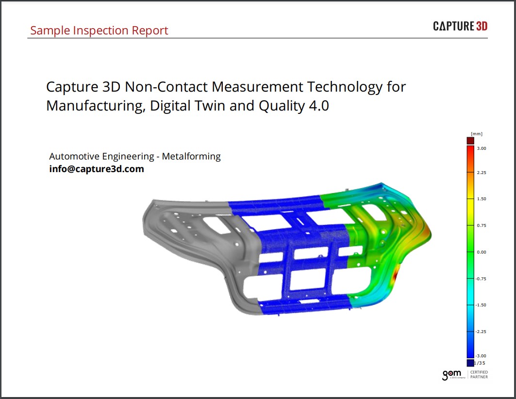
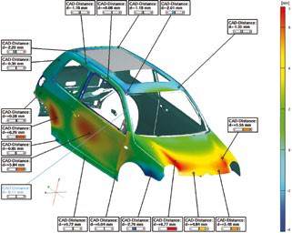
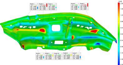
After alignment, the deviation of each data point to the CAD can be determined. Using the digitizing measuring data, a full surface color 3D display of the deviations to the CAD can then be created. Local deviations can be analyzed using inspection sections.
|
|
|
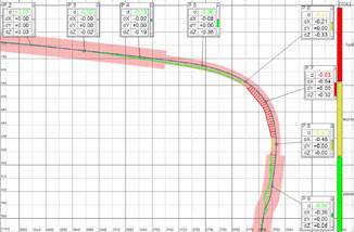
When checking the borders, a distinction can be made between normal deviation (springback) and tangential deviation (trim). In addition to the planar target/actual comparison, the Trim & Springback and hole pattern measurement can be analyzed with the system hemmed edges as well as Gap & Flush.
|
|

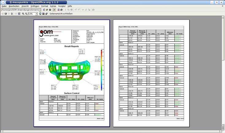
Measuring results can be created in customizable configurable reports. In addition to images, all values can be exported to tables, Word, Excel, or HTML format. In addition, the free ATOS 3D Viewer supports the comprehensive use of 3D coordinate measuring data and their evaluation. All 3D measuring data and inspection results are available in compressed format for exchange and further processing by customers and colleagues.
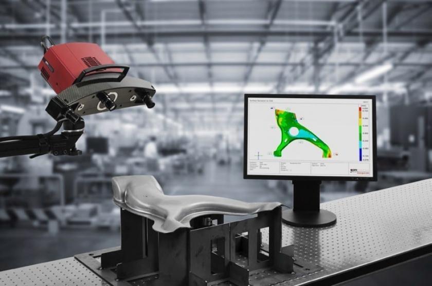
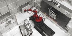
Automated measuring cells: process security and trend analysis
Flexible, automated inspection cells can be realized in conjunction with robots, turntables, and linear positioning units. The full-surface component measurement enables a simple good GO / NO GO statement. It also shows the course of deviations for a fast evaluation of processes. This means early detection of potential problems so that processes can be corrected in a timely manner, resulting in lower production costs and efficient quality control.
 |
 |
Optical 3D measuring techniques: an advantage for the sheet metal forming industry
Companies that implement optical measuring techniques benefit from shorter production times for products as well as the shorter series start-up times. Companies remain competitive because they help their customers go from idea to product faster, optimize production workflows, and minimize rejects while production is running. Particularly in terms of automated measuring cells, the single-source, comprehensive approach from measuring hardware to evaluating inspection software, in conjunction with training and support, represents a significant advantage.