3D Scanning of a Die-Cast Mold for a Protective Mask
![]()
![]()
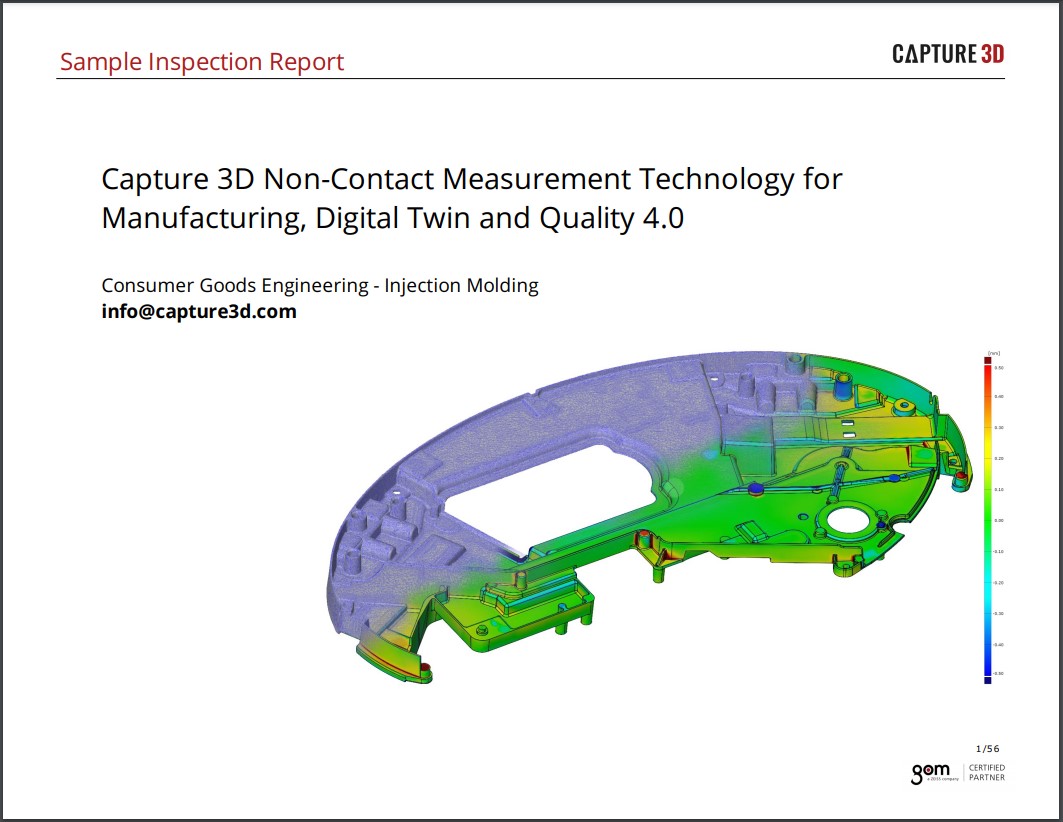
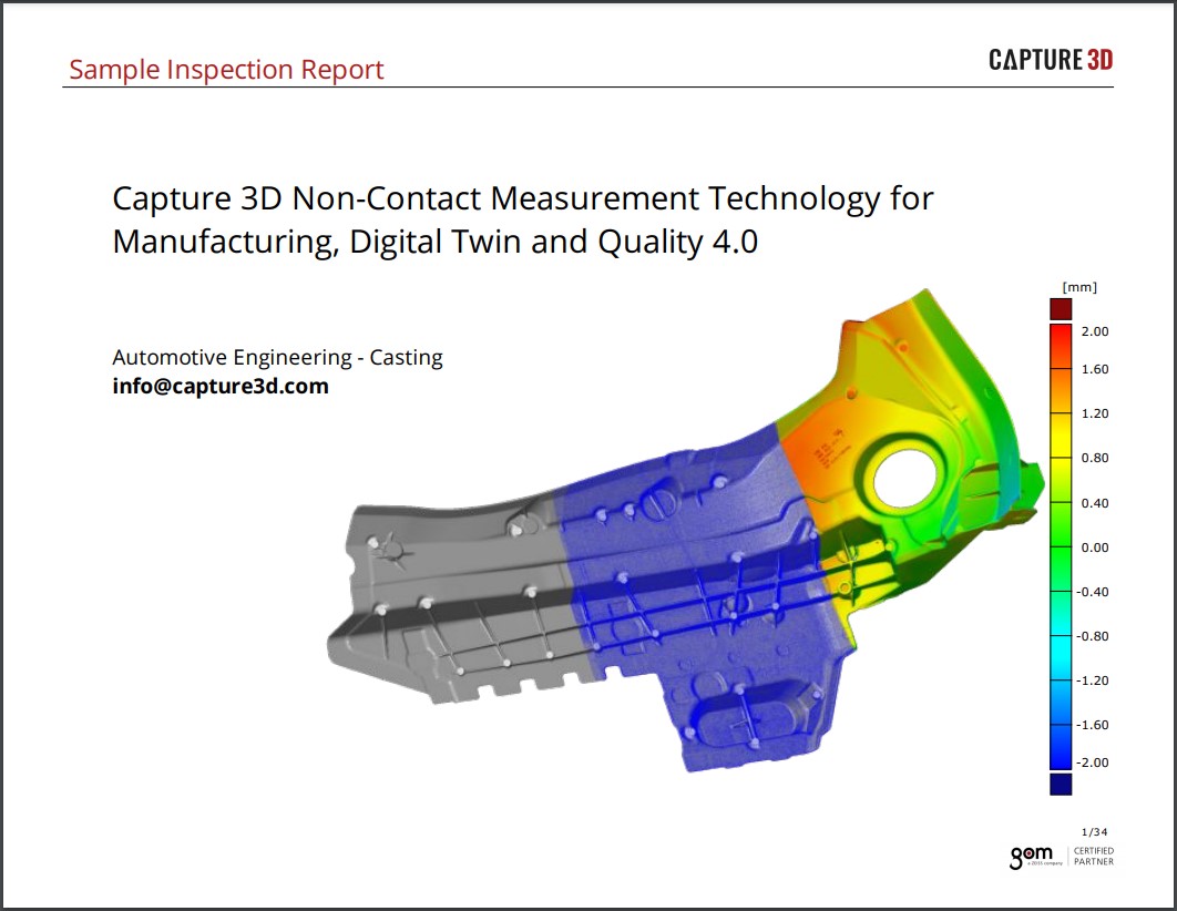
Manufacturing tooling for processes such as casting, deep drawing, progressive forming, forging, stamping and injection molding undergo an important design phase where various manufacturing factors need to be calculated and optimized in such as draft, shrink, spring back etc. For example, a mold is not simply the negative of the product to be manufactured. The physical characteristics during shaping (elasticity, shrinking behavior, flowing behavior, etc.) have to be taken into account and require an "incorrect" mold in order to produce the dimensionally correct parts.
It is here, that optical 3D scanner has proven itself an effective method to optimize a tool and define and monitor its dimensional stability. For example, the high-quality ATOS 3D scanner can be used during initial sample testing to capture and describe the manufactured parts as a highly accurate dense point cloud. The ATOS software also supports the comparison of the measured data of a tool part with its predefined shape in the CAD data. Possible deviations are displayed on the screen in an intuitive color map thus highlighting necessary changes. So, modifications to the shape of a tool can be carried out efficiently. The modified mold is then digitized and its optimized shape is saved as reference data set. In addition, the measuring data (stl mesh data or section data in vda, iges or ASCII format) allows for tracking the CAD data set in order to update the production documents so they reflect the optimized tool. This provides the ability to duplicate the tool set while saving both time and money. When designing similar tooling, the digitizing system will assist you in generating a database of tooling characteristics based on the experience from existing molds. Now, you can easily draw upon optimized and well-proven molds to recreate broken tooling or revise existing tools.
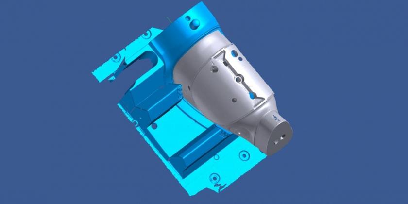
Using 3D scanning, it is also easy to duplicate an existing tool. The dense point cloud that results from the measuring data is transferred into a CAD surface model using surface reconstruction. However, it is also possible to use a numerical machine tool which, with the help of a CAM software, directly mills on the data sets generated by ATOS. The advantage of such a method is that it is really fast. Scanning requires just a short time and does not cause long machine downtimes. In addition, you can perform digitizing work during machine maintenance. The latter method was used for the following task.
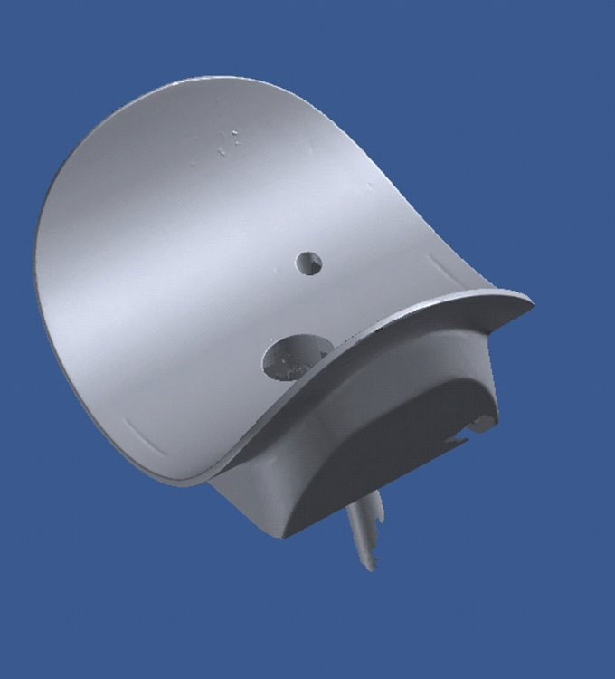
The object
The gas mask consists of a single part with integrated fixings, sealing membranes and filter supports. This requires a very complex die-cast mold.
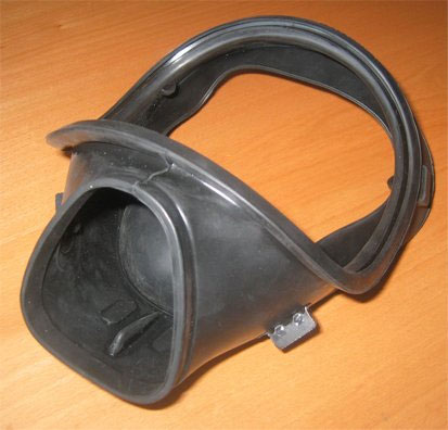
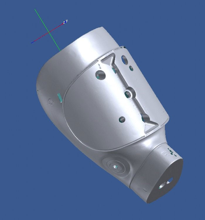
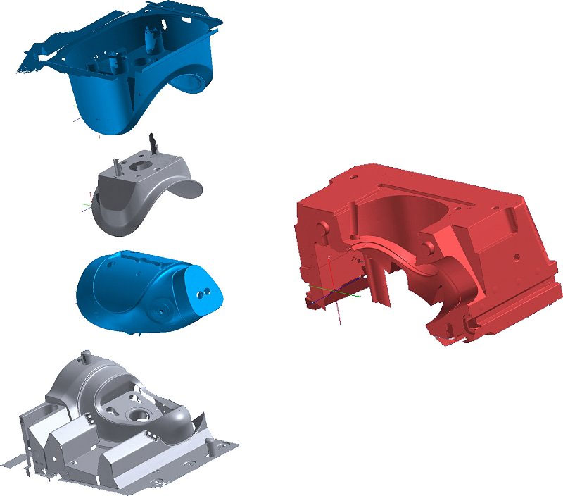
The tool
Several areas have to be die-cast in an overlapping way. That is why the mold contains several parts (main elements, inserts, cores, …) which each create a part of the mask. The closed tool results in a compact, tight die-cast mold in which the material is injected. The small material thickness of the mask, the tightness of the tool parts among each other and the accuracy of the mask with respect to the CAD specifications are problematic.
The challenge
The 3D data of the entire tool including all inserts have to be recorded in the workshop next to the injection press during an intended maintenance period of 5 hours.
Procedure
For digitizing, the ATOS II 3D scanner and TRITOP photogrammetry are used. In order to guarantee the exact reference of the various elements, all parts are recorded in their current position in the predefined coordinate system of the tool.
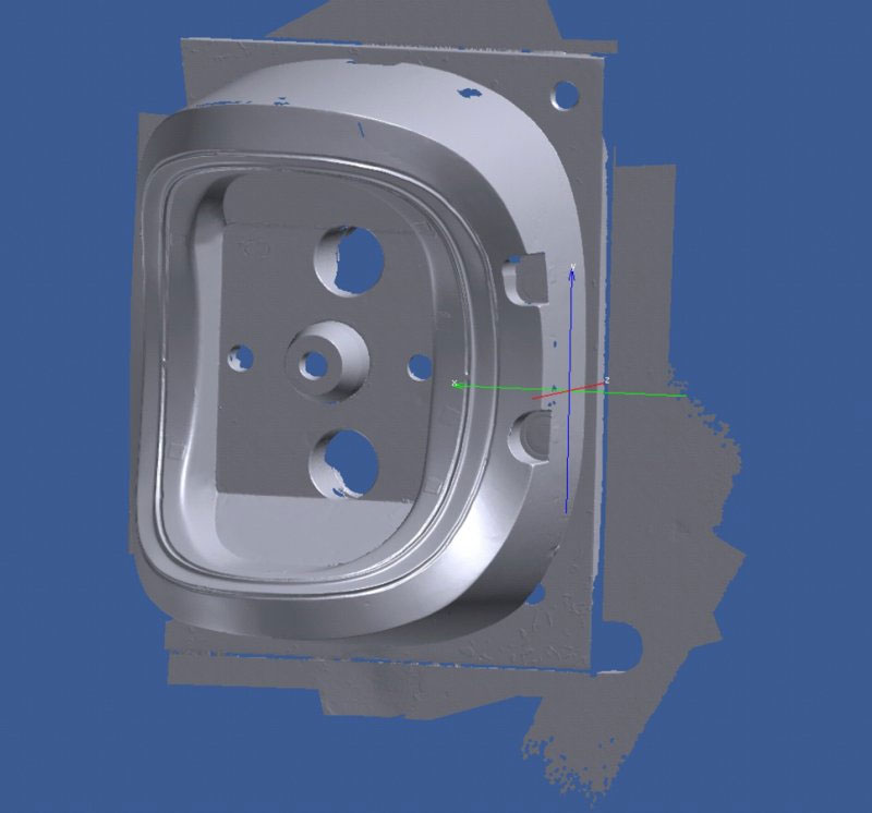
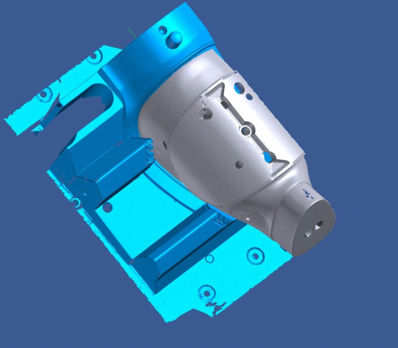
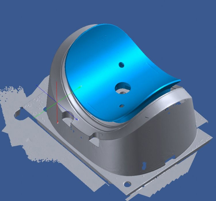
In a first phase, the closed mold is digitized. For this purpose, at least three reference points are applied to the outer surfaces of each individual part. The GOM digitizing system records and defines these points in the coordinate system of the tool. If you now take the mold apart, these "fixed points" move together with the respective elements. Then, the individual parts can be digitized in their dismounted state while the data will show the "correct" coordinates of the closed mold.
 |
 |
 |
 |
 |
 |
 |
 |
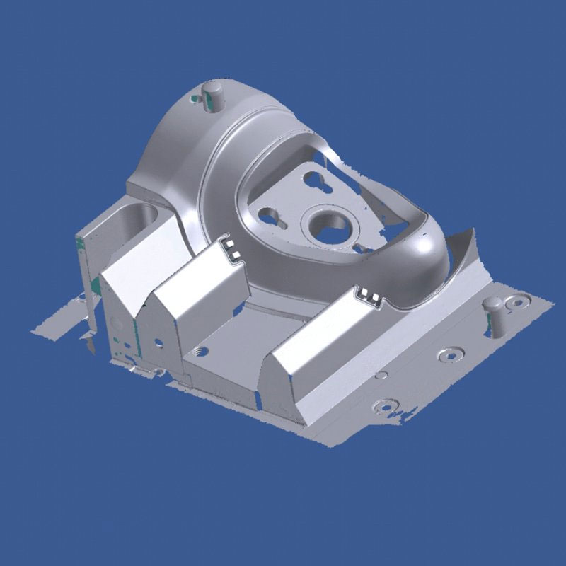
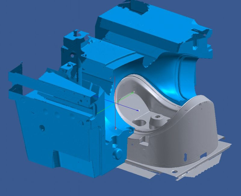
GOM's photogrammetry system TRITOP optimally supports this technique. It records the exact position of the exterior reference points. When opening the mold, additional reference points are applied to the new visible areas and in a second phase, they are recorded in the predefined coordinate system of the tool. The ATOS 3D scanner then uses the positions of the reference points defined in TRITOP photogrammetry to digitize the shape of each individual part in the predefined coordinate system. The interplay of these two precise measuring technologies and their compatibility is the key to allow for measuring the exact shape of complex objects.
Measuring accuracy
The digitizing systems of GOM process redundant information to verify the system calibration and the measuring accuracy. This guarantees reliable certification of the GOM digitizing systems and makes them a valuable instrument for quality control and toolmaking.
The photogrammetry system TRITOP evaluates the images taken from numerous positions and is able to calculate the 3D coordinates of each reference point and optimizes and protocols the quality of this image set. The system calculates the exact position of the reference points from at least three images, stating the statistical value of the deviations of the image intersection points.
During digitization, the ATOS system automatically records these calculated positions with the help of two cameras (stereo vision) and generates the 3D surface (point cloud) of the object to be measured from several individual images. In addition, the system evaluates and positions the current measuring data into the reference point data coordinate system established by the TRITOP system.
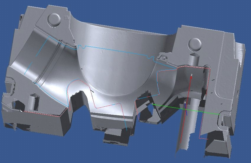
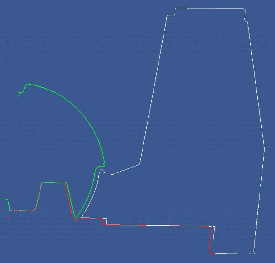
In order to verify the accuracy of the measuring data, the material thickness of critical areas was calculated using ATOS. Measurements of the mold parts confirm their tightness, and the material thickness was checked on the final mask.