Scan to CAD Alignment Methods in GOM Inspect Software
Three-dimensional scan data is collected independently of any datum structure, so all alignments are performed after the mesh is created. Any conceivable alignment is computed within the software if there is enough quality scan data on the alignment surfaces.
Occasionally other surfaces such as a fixture plate are also referenced as a datum surface. The ability to toggle in and out of alignments provides a versatile platform to assess your own production process, or simply to inspect any part.
Having the ability to easily try different alignments allows you to quickly test and verify multiple possibilities for adjustments and troubleshooting. Keep reading to learn more about how to use GOM Inspect to streamline your inspection process with the most common alignment methods. Or go ahead and watch Dane's in-depth video tutorial on this subject below.
7 Methods To Align Your Scan To Cad Data In Gom Inspect
1. 3-2-1 Alignment
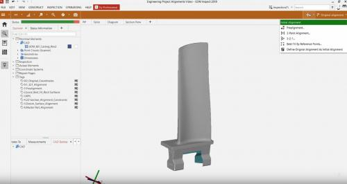 Begin by accessing the inspection workspace in the drop-downmenu on the upper left portion of your screen, directly below the file tab.Your workspace can be pinned or unpinned using the option to the left of your screen.
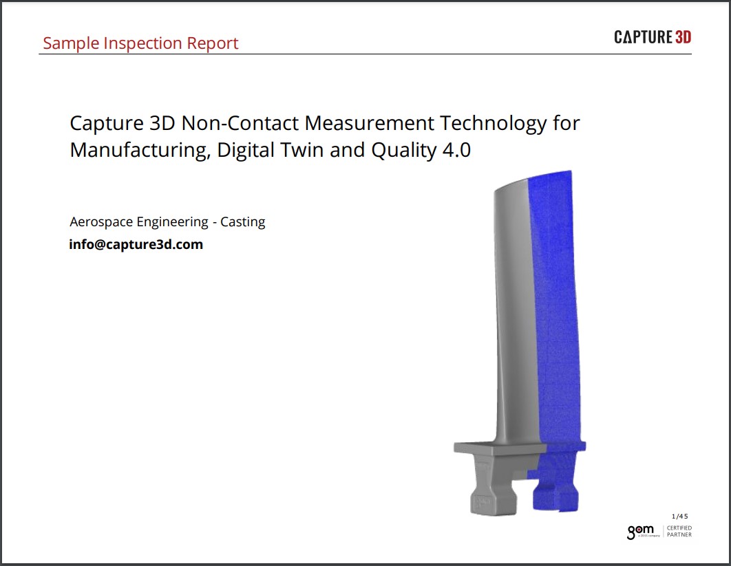
An aerospace project will be used throughout this article to highlight the most common CAD part alignments in GOM Inspect. If you want to analyze a part without having any CAD, then you can create a 3-2-1 alignment.
In the upper right portion of your screen, open the "Create Alignment" drop-down menu. Choose 3-2-1 and find the surfaces you want to square up in space. Choose three points for your primary datum,two points for your secondary datum, and one point for your tertiary datum. Then, hold the CTRL button while left mouse clicking the desired points.
Next, click OK to create this alignment. By manipulating the coordinate cube at the bottom left of the 3D view, the mesh is now squared up inspace using the respective surfaces. At this point, you can construct your required features and begin inspecting this part as if it were the intended coordinate system.
By clicking the F10 button, you can visualize the coordinate system as it lies on the mesh. By hitting F9, you can make the coordinate system disappear.
2. Prealignment
To begin the initial alignment, import both the CAD and mesh for your scan data into the free GOM Inspect software 2019. These two elements naturally come in with different coordinate systems.
Whenever you create an alignment in the software, you are moving everything else around, so the mesh comes in alignment with the CAD or your nominal data. With both parts now imported, you can create your prealignment.
Most of the time, projects begin with a prealignment. All other subsequent alignments are initiated from this starting point.
The prealignment is a global best fit between the CAD and the mesh that minimizes all deviations between both nominal and actual surfaces. If no datum structure exists for your part, the prealignment is a very nice place to start.
If you need to choose a health point, simply click on the CAD, and click on the mesh in relatively the same area, which helps to create the prealignment for more symmetrical parts. Once you're done, hit OK, and your prealignment is created.
3. Local Best-Fit
In many cases, you'll need to align datuming surfaces to see how multiple parts may interact. These might not necessarily be your datum surfaces.
You can use a local best-fit alignment on the root area of this blade to highlight this process.
Next, go to the edit menu and find the plane-based selection tool, which allows you to select data on the mesh where you want to force your localized alignment.
Hitting CRTL+R brings back the most recently used selection tool.
Next, go to the "Create Alignment" drop-down menu, choose "Local Best-Fit"and hit OK. After this root-based alignment, the upper portion of the blade behaves as it would sit in the rotor assembly.
4. RPS (Reference Point System) Alignment
Another common alignment is the RPS alignment, which stands for reference point system. This alignment type allows you to reduce the overall deviation of a discrete number of points, surface points, or other datum points.
In this phase, you have already constructed your six-point nest alignment points using TouchPoints. Next, drop down the create alignment menu and open the RPS dialog. Then, pull in your six points using the button at the bottom left of this window after you've highlighted the necessary points.
The software intuitively knows which direction each point should be constrained.
The midpoint, for example, is best constrained in the XY plane, and the Z point should constraint at Z. In any of the alignment dialogues with a based-on option,the selection here will dictate which alignment is your start point for the new alignment. Then, click OK to create this alignment.
By giving each RPS point a dN in check, the software minimizes the deviation of all points.
5. 2D Section
GOM Inspect software also allows you to align these sections of this airfoil accurately. Imagine you want to analyze the cross-section of this airfoil independent of its overall form.
First, select the desired section, choose "Local Best-Fit," and provide constraints. In "Edit Global Constraints," define which degrees of freedom are allowed. You may enable X and Y Translation and Z Rotation, but this decision is relative to the alignment based on your prealignment.
Next, move forward using the airflow package in the ATOS software. The function profile form and position create a similar alignment when checking the cross-section.
6. Datum System Alignment
Several types of features are available to create a geometric elements alignment to complete a datum system alignment.
You can use features like circles, cylinders, points, lines, planes, and more. You can construct features that are referenced as your primary, secondary, and tertiary datums. Once you create three planes for the alignment and give the appropriate measuring principle, open the "By Geometric Elements" alignment.
Next, choose your primary, secondary and tertiary features.Then, the software automatically pulls in the correct actual element. You can choose not to use these defaulted elements by choosing another option in the drop-down menu.
If the software shows a warning, it does not let you click OK. Your features may not be constrained at all six degrees of freedom properly.Click OK to create this alignment.
7. Master Part Alignment
The Master Part Alignment is another local best-fit alignment that combines your section and root alignments.
This idea is inspired by a recent customer who uses a master part to calibrate the machine they check parts with. This alignment replicates a root fit in addition to a cross-section fit using the convex side of the blade.
Choose the correct actual data on the mesh to create this local best-fit. With this alignment, you've constrained the root as well as the upper portion of the blade.
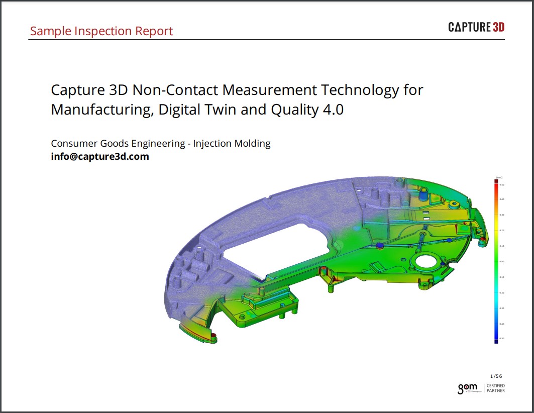
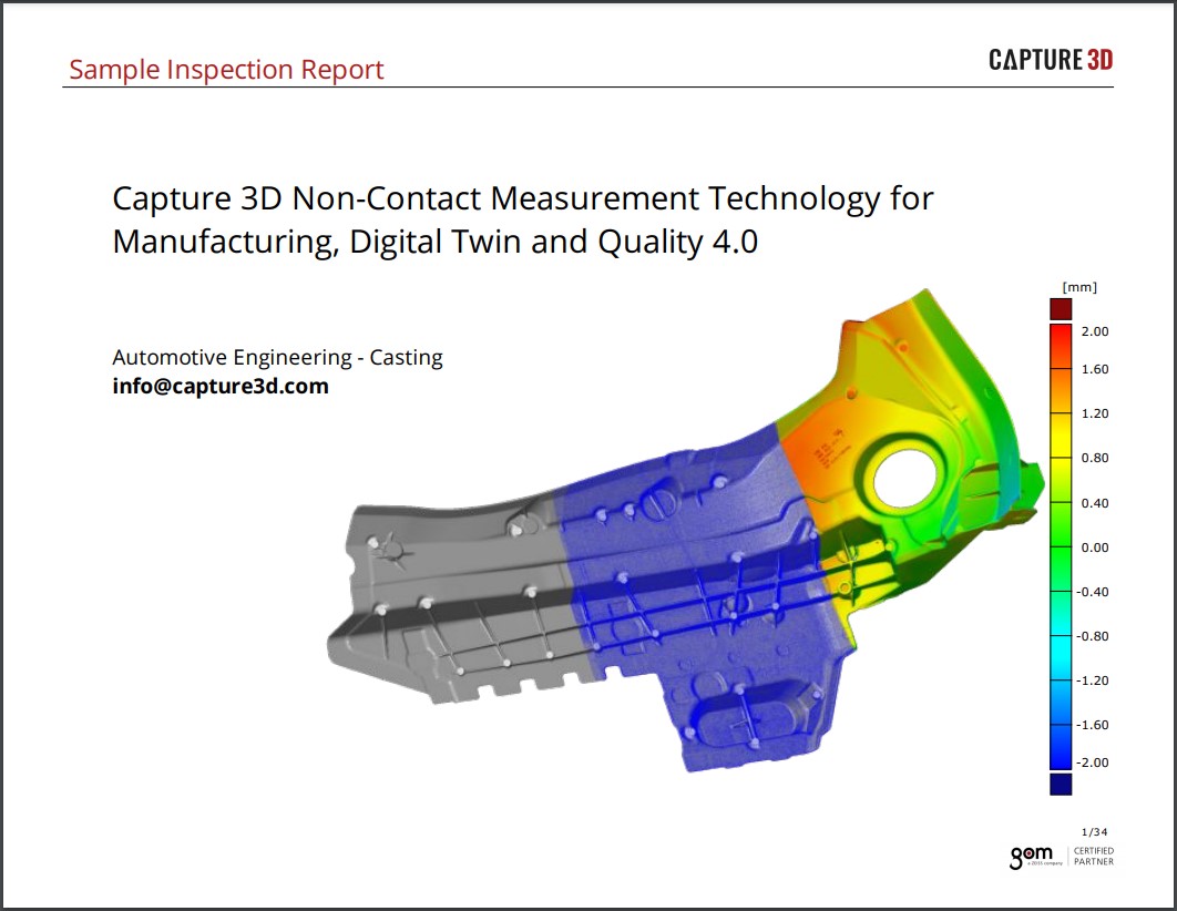
Summary & Surface Comparison
Once you've done the work to create your alignment, check the surface comparison to see the results. Choose "Surface Comparison on CAD," leave the defaulted parameters that arealready set, and click OK.
Next, add a few deviation labels so you can get numerical values of the deviation between CAD and mesh. Then, you can see the color map in the prealigned state.
You'll see your Datum System alignment, your Master Part alignment, your Root Fit alignment, your 2D-Section Fit alignment, and your RPS alignment.
Beyond these common alignments, there are best practices for the alignment of certain types of parts, but ultimately the choice is up to you. To learn more about how and why you might choose a specific CAD part alignment, contact a Capture 3D expert today or click here to schedule a demo.