GOM Software - What is the I-Inspect Wheel?
The I-Inspect function, or I-Inspect wheel, provides access to inspection options for any element selected within your project. Regardless of what scanner or measuring volume you use to scan your part, you'll likely be using the I-Inspect function to inspect those parts. To open the I-Inspect wheel, simply left mouse click on the magnifying glass icon within the inspection workspace or within any workspace use the hotkey, which is CTRL plus right mouse click in the 3D view.
What are the Benefits of the I-Inspect Wheel?
The I-Inspect wheel can help you manage inspection functions, guide you through the inspection process by only offering necessary and relevant inspections and checks, and automatically identify selected elements, whether actual or nominal. The I-Inspect wheel can be displayed as two different menus, depending on which skin you're working on in your project, whether it's the inspection skin or the deformation skin.
What are the Functions of the I-Inspect Wheel?
To see the I-Inspect wheel's functions, open it by clicking on the magnifying glass icon in the inspection workspace or use the hotkey in the desired location within the 3D view. Notice that when the I-Inspect wheel is open, it's essentially a pie wheel with five pieces and a center edit icon.
How to Use the Measuring Principle Function
The first icon is a T symbol denoting the measuring principle function. The available measuring principles will vary depending on the type of elements selected because the I-Inspect wheel will only generate elements relevant to whatever is selected. In GOM Software, a measuring principle tells the software how to create a corresponding actual element based on the created and selected nominal element. This example uses a GOM training block. First, select a surface point, hit the T symbol, and select "Intersection with Mesh" to create an intersection with mesh. An intersection with mesh is the vector of the created nominal surface point going in either direction until it intersects with the mesh, where the actual surface point will be placed.
How to Use the Check Function
Moving around the I-Inspect wheel, the next button is for checks. The type of element selected determines the type of checks available. For example, on the GOM training block, select a surface point, click on the I-Inspect wheel's check icon, and select the normal deviation option. By clicking on the various elements, you can see the different checks available, such as a cylinder's radius.
This next icon is for GD&T inspections. Like with the other elements, the available list of options the I-Inspect wheel provides depends on the type of element selected. For example, on the cylinder, you can check the roundness of the cylinder. However, selecting the surface point provides a much shorter list. For this example, choose the true position option, fill out the dialog box, and click OK.
How to Use the Airfoil Inspection Function
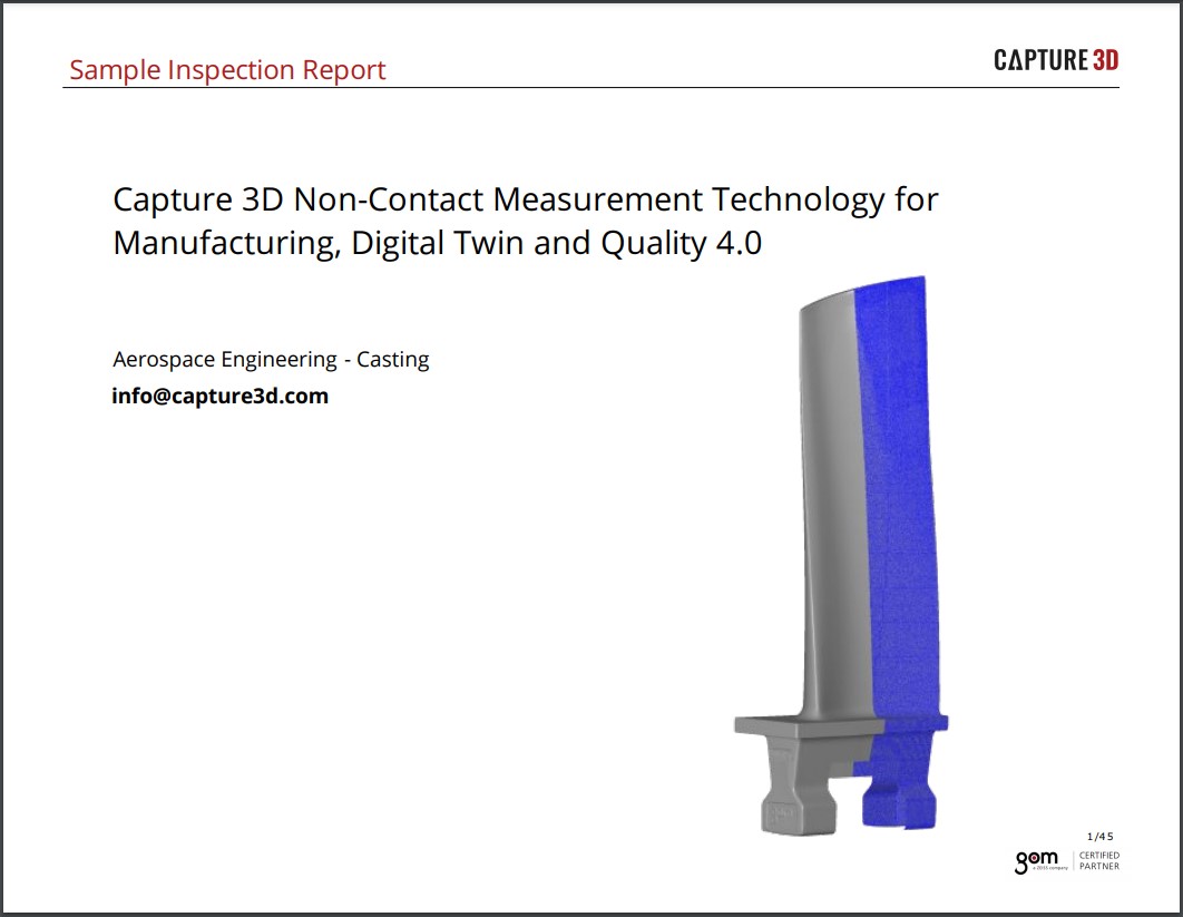
The next icon is solely for airfoil inspections. A section must first be cut through the airfoil to utilize the I-Inspect wheel's airfoil inspection function. Once that is done, select it and hit the "E" key to make that section exclusive. Then, with that section selected, left mouse click the airfoil icon and apply any of the available checks.
However, if you don't work in the airfoil or aerospace industry, and you never intend to use the airfoil icon, you have the option to customize the I-Inspect wheel by navigating to "Inspection," then "Configure I-Inspect." By left mouse clicking on the airfoil button, the icon will then disappear.
How to Use the User-Defined Inspection Principle (UDIP) Function
The next icon, which looks like the silhouette of a person holding a frisbee, is the user-defined inspection principle, also known as the UDIP. The UDIP is an easy way to group and save repeating element inspections and essentially create a standard procedure for a specific type of element. This example will check cones on the GOM training block for their angle and straightness. Instead of checking each cone one by one, you can select all the cones and then click on the UDIP button for the desired previously created UDIP. By left mouse-clicking, you'll notice that instantly all the inspections are automatically completed and labeled.
How to Use the Edit Button
Finally, the center icon is the edit button, which provides an element frontal view. It also allows you to recalculate an element, edit creation parameters, or choose from several visualization options, such as displaying only the selected element's name.
Continue Increasing Your Inspection Efficiency
The I-Inspect wheel offers helpful shortcuts to quickly access and perform essential inspection functions for increased efficiency. Beginning with a nominal element within the software, functions on the I-Inspect wheel generate an actual element by applying a measuring principle. Then, I-Inspect wheel functions allow you to apply checks and GD&T inspections to that element in just a few clicks. The I-Inspect wheel's airfoil icon enables you to perform a basic airfoil inspection quickly, and the UDIP function applies automatic inspections to multiple elements. But the I-Inspect wheel is just one way GOM's intelligent software solutions create a truly user-friendly experience. To learn more about how to use these software solutions to increase the efficiency of your digital engineering processes, contact a Capture 3D team member today. Our team members will be happy to show you a demo and help you find the solutions that best meet your requirements.